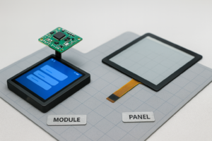
As advanced electronic devices become more common, the demand for intuitive Human-Computer Interaction (HCI) has skyrocketed. This evolution places simplified capacitive touch sensing technology at the forefront, changing how we interact with the world around us.
While resistive touch has its place, simplified capacitive touch sensing has emerged as the superior approach. Its advantages are clear: no mechanical parts to wear out, a longer lifespan, higher sensitivity, and greater design flexibility for rich gestures. In response, integrated circuit (IC) manufacturers constantly release new chips that make using this powerful technology faster and easier for hardware engineers.
The Core Principles of Capacitive Touch Sensing
Essentially, modern ICs that enable simplified touch use one of two main methods to detect a touch:
- Capacitance-to-Voltage Conversion: This method converts changes in capacitance from a user’s touch into voltage changes. A specialized internal analog-to-digital converter (ADC) then samples this voltage to precisely calculate the capacitance value.
- Capacitance-to-Frequency Conversion: With this technique, the system translates capacitance changes into a different count value in a digital counter. It works by generating a triangle-wave charge and discharge signal on the external electrode. The system then measures the period of this waveform, which accurately reflects the electrode’s capacitance.
Streamlined Hardware Design
Using an MCU with a dedicated capacitive touch module makes the hardware design process very straightforward. This approach not only reduces development costs but also minimizes circuit complexity, leading to a more stable and robust final product that benefits from simplified capacitive sensing.
Touch Interface Design
An integrated Touch Sensing Input (TSI) module is key to this simplicity. For instance, an engineer only needs to connect an external electrode to the correct TSI channel through a single current-limiting resistor. This resistor plays a crucial protective role, preventing high charge currents from damaging the MCU. Engineers choose the exact resistance value based on the application’s specific requirements.
PCB Layout for Touch Keys
Furthermore, engineers can create the touch keys directly on the Printed Circuit Board (PCB). A popular technique involves using copper pads, coated with an insulating solder mask, to act as the electrodes. For example, arranging triangular copper fills to form a larger square touch key is highly effective. Each triangular section then connects to a separate TSI channel, which allows for more advanced features like position tracking or multi-touch gestures thanks to simplified capacitive technology.
Efficient Software Implementation
A dedicated TSI module doesn’t just simplify hardware; it also streamlines software development. Specifically, developers can drive touch functionality simply by configuring a few registers, running a calibration routine, and writing a simple interrupt service routine. This process greatly speeds up the entire software design flow for capacitive sensing.
As a result, this design creates a highly efficient system. The TSI module automatically and periodically scans the electrodes without constant CPU oversight, which significantly reduces the processing load.
1. TSI Module Initialization
First, developers set up the TSI module by configuring its internal registers to match the hardware. This involves setting key registers such as:
- General Control and Status Register (e.g., TSI0_GENCS)
- Scan Control Register (TSI0_SCANS)
- Channel Enable Register (TSI0_PEN)
In addition, developers must also configure the MCU’s internal clock and pin settings to support the TSI function.
2. TSI Module Self-Calibration
Next, the developer must calibrate the TSI module to establish a reliable baseline for touch detection. This critical step works as follows:
- The system measures the natural capacitance of the electrodes when they are not being touched and records this as the baseline count.
- It then creates a “deadband” by adding and subtracting a set offset value from this baseline.
- Finally, it stores these new values in high and low threshold registers.
This process ensures that an “out-of-bounds” interrupt triggers only when a real touch event causes the capacitance to cross outside these thresholds.
3. Handling TSI Interrupts
The TSI module can generate several types of interrupts, including error, timeout, end-of-scan, and the crucial out-of-bounds interrupt. In many MCUs, these events share a single interrupt vector. Therefore, the interrupt service routine must identify the event and respond correctly—for example, by confirming a touch and running the desired action within a simplified capacitive sensing structure.
Conclusion: Practical Application in Modern Devices
This simplified capacitive touch sensing approach is the engine behind today’s most convenient and practical HCI devices. All-in-one touch computers, for example, use this streamlined method to seamlessly integrate computing, multimedia, audio, and networking. With sleek designs and a superior touch experience, these systems make information access truly effortless, proving the power of well-designed, intuitive human interaction.
.png)


