
Transportation · OEM touch integration
Custom Touch Displays for Transportation Equipment OEMs
From the driver’s console to the passenger terminal, start with the touch and display assembly your equipment needs.
EverGlory supports PCAP selection, bonded LCD module development and industrial monitor integration. Bring your drawing and host requirements to review glass, FPC routing, interfaces, mounting and sample validation.

A custom touch panel for an existing LCD, a bonded touch display module, or a monitor assembly for an external host. Vehicle electronics, software and installed-equipment qualification remain part of the OEM’s system integration.
01 / Application positions
Where will the interface work?
Installation position changes the optical, mechanical and electrical review. Select the closest application to start the conversation.
Driver consoles & fleet terminals
- Installation
- Dashboard or bracket-mounted operator interface.
- OEM purchase
- A console interface matched to the existing fleet host.
- Supply scope
- Custom PCAP panel or bonded touch-LCD module.
- Fit priorities
- Day/night readability; glove type and touch interface; mounting vibration and cable retention.
USB or I²C is assessed against the selected controller and host; LCD video is a separate interface decision.

Onboard HMI & maintenance interfaces
- Installation
- Cab console or onboard service interface.
- OEM purchase
- Display hardware for a railway equipment HMI.
- Supply scope
- Touch-display subassembly or monitor; vehicle control electronics stay with the OEM.
- Fit priorities
- Shock/vibration and EMC criteria; thermal profile; panel availability and revision control.
EN 50155 and IEC 61373 are review inputs where applicable. This page does not identify a railway-certified product.
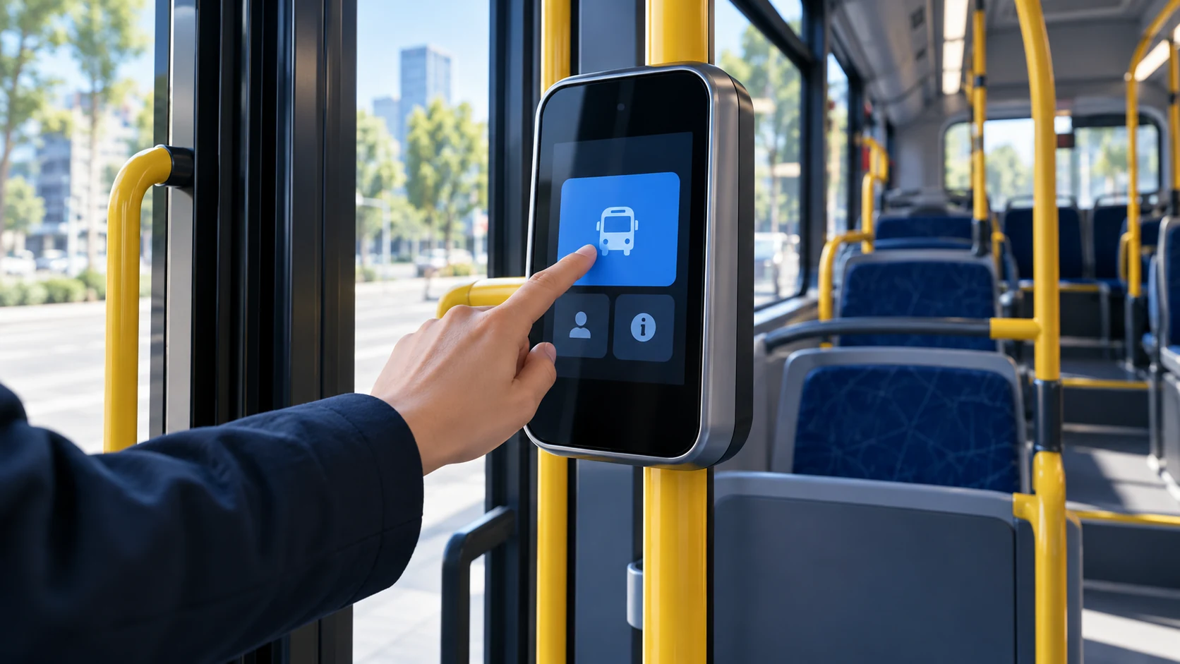
Onboard information & ticketing
- Installation
- Passenger-facing terminal inside the vehicle.
- OEM purchase
- A passenger-facing touch interface, where interaction is needed.
- Supply scope
- Touch-LCD module or open-frame monitor; no fare/payment subsystem.
- Fit priorities
- Cleaning and abrasion; glare and front protection; service access and mounting.
Display-only signage may not need touch. Fare validation and payment certification sit outside the display supply scope.

Mobile machinery & service vehicles
- Installation
- Operator cab or equipment-mounted control terminal.
- OEM purchase
- Touch hardware for an OEM cab or equipment enclosure.
- Supply scope
- Custom cover glass and PCAP, or a touch-display module.
- Fit priorities
- Glove/wet interaction; sensor and LCD noise; enclosure heat and cable routing.
Glove response and sealing need checks on the chosen assembly. Passenger-car infotainment qualification is a separate review.
Application-to-supply selection guide
Swipe to compare all columns ↔ · Keyboard: focus the table and use the arrow keys.
| Installation | Starting supply level | First decision to resolve |
|---|---|---|
| Bus / fleet console | PCAP panel or bonded module | Existing host, optical stack and dashboard fit |
| Rail HMI / maintenance | Module or monitor subassembly | Applicable equipment standards and validation boundary |
| Onboard passenger terminal | Touch module or open-frame monitor | Whether touch input is needed; cleaning and service access |
| Special vehicle / machinery | Custom PCAP or touch module | Gloves, enclosure conditions and host integration |
02 / Supply options
Choose your integration level.
Define what stays in your design and what the touch/display supplier delivers.

01 / COMPONENT
Custom PCAP & cover glass
For OEMs keeping their LCD, host and enclosure.
- Supply scope
- Glass, sensor, FPC and controller arrangement defined in the reviewed drawing.
- Bring to review
- OD, VA/AA, cut-outs, edge finish, cable exit and host interface.
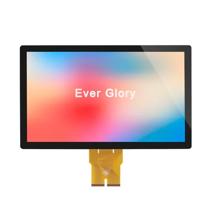
02 / OPTICAL ASSEMBLY
Bonded PCAP + LCD module
For a touch and display stack built around your mechanical envelope.
- Supply scope
- Selected LCD, PCAP and agreed bonding stack, with defined display and touch connections.
- Bring to review
- LCD specification, optical needs, lens drawing, available depth and mounting limits.
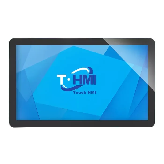
03 / MONITOR ASSEMBLY
Open-frame touch monitor
For equipment using an external computer or vehicle host.
- Supply scope
- Monitor architecture, video input, touch return, power and mounting agreed for the assembly.
- Bring to review
- Host outputs, power source, bracket drawing and thermal/service requirements.
Product family images. The monitor image shows a housed example; an open-frame build needs a separate assembly drawing. OD = outside dimensions; VA = viewing area; AA = active area.
Module or monitor: who owns the integration?
Bonded module
The OEM normally owns the host, system power design, video interface electronics and enclosure. The module quotation defines the LCD, touch controller, bonding stack and connections it includes.
Monitor assembly
The quotation defines the included display driver, supported video/touch interfaces, power input and mounting. The OEM still owns vehicle power compatibility and final enclosure/equipment qualification.
03 / Engineering requirements
Turn operating conditions
into a validation plan.
The installed system matters: glass, LCD, controller, power, wiring, enclosure and mounting all affect the result.
Engineering selection reference · Final specifications depend on the selected product and installed equipment.
| Review area | Inputs from the OEM | Engineering decision |
|---|---|---|
| Day & night readability | Ambient light, viewing angle, target luminance and minimum dimming level. | Review LCD, cover finish, bonding and host-controlled dimming. Brightness alone does not establish sunlight readability. |
| Glove, wet & condensation | Glove material/thickness, water exposure, cleaning agents and operating sequence. | Choose controller settings and agreed sample checks. A glove or wet-touch illustration is not a test result. |
| Shock, vibration & mounting | Bracket, fixing points, cable restraint, load profile and applicable test method. | Review mechanical integration, connectors and installation-level testing; no universal vibration rating. |
| EMI, ESD & grounding | Host, LCD, power topology, cable lengths, earth path and required limits. | Plan shielding/grounding and functional checks on the assembled equipment. Internal checks do not certify the vehicle. |
| Thermal range & sealing | Separate operating/storage limits, solar load, duty cycle, enclosure airflow and required IP boundary. | Assess every stack component. An IP claim requires a matching test for the defined front assembly, gasket and enclosure. |
| Lifecycle & change control | Program life, forecast, service strategy and notification requirements. | Agree the drawing/BOM baseline, revision traceability and change review. Availability commitments belong in the supply agreement. |
Inputs from the OEM Ambient light, viewing angle, target luminance and minimum dimming level.
Engineering decision Review LCD, cover finish, bonding and host-controlled dimming. Brightness alone does not establish sunlight readability.
Inputs from the OEM Glove material/thickness, water exposure, cleaning agents and operating sequence.
Engineering decision Choose controller settings and agreed sample checks. A glove or wet-touch illustration is not a test result.
Inputs from the OEM Bracket, fixing points, cable restraint, load profile and applicable test method.
Engineering decision Review mechanical integration, connectors and installation-level testing; no universal vibration rating.
Inputs from the OEM Host, LCD, power topology, cable lengths, earth path and required limits.
Engineering decision Plan shielding/grounding and functional checks on the assembled equipment. Internal checks do not certify the vehicle.
Inputs from the OEM Separate operating/storage limits, solar load, duty cycle, enclosure airflow and required IP boundary.
Engineering decision Assess every stack component. An IP claim requires a matching test for the defined front assembly, gasket and enclosure.
Inputs from the OEM Program life, forecast, service strategy and notification requirements.
Engineering decision Agree the drawing/BOM baseline, revision traceability and change review. Availability commitments belong in the supply agreement.
04 / Documented engineering reference
A defined module.
A clear starting point.
15.6-inch touch display module
A published engineering summary shows how dimensions, display characteristics and touch requirements are recorded before a sample is released.
Non-transport-specific reference. These are documented specification values and acceptance targets, not a railway approval or an all-model test result.
- Display definition
- 1920 × 1080
500 cd/m² typical; 1000:1 typical contrast - Touch configuration
- 10-point PCAP · USB
5 V typical supply - Mechanical definition
- 380.56 × 229.99 mm cover outline
12.7 mm overall stack; 2.9 mm touch panel - Functional acceptance targets
- ≥100 Hz report rate · ≤25 ms response
±2 mm linearity — requires matching validation - Optical / material criteria
- >85% transmittance · ≥6H cover hardness
Specification criteria, not test-pass evidence
Source: EverGlory Engineering Capabilities, accessed 28 October 2026. Request the matching controlled specification for procurement.
05 / Prototype to production
Agree the inputs.
Control the sample baseline.
Each review step should produce a decision or a record that the next team can use.
- 01
Drawing & requirements
Capture the installation, envelope, interfaces and target conditions.
Output: review inputs - 02
DFM & risk review
Check glass, stack-up, FPC, grounding, bonding and assembly constraints.
Output: open-item list - 03
Controlled sample
Agree the drawing revision, LCD/controller and functional checks.
Output: sample baseline - 04
Installed validation
Evaluate the host, enclosure, cables and agreed environmental tests.
Output: scoped results - 05
Production quality gates
Release inspection criteria, traceability and change-control responsibilities.
Output: release records
See how production quality and revision traceability support the agreed build.
06 / Engineering evidence
See the work behind the assembly.
Published drawing summaries, factory equipment and internal checks show the review process. They do not establish a transport qualification.
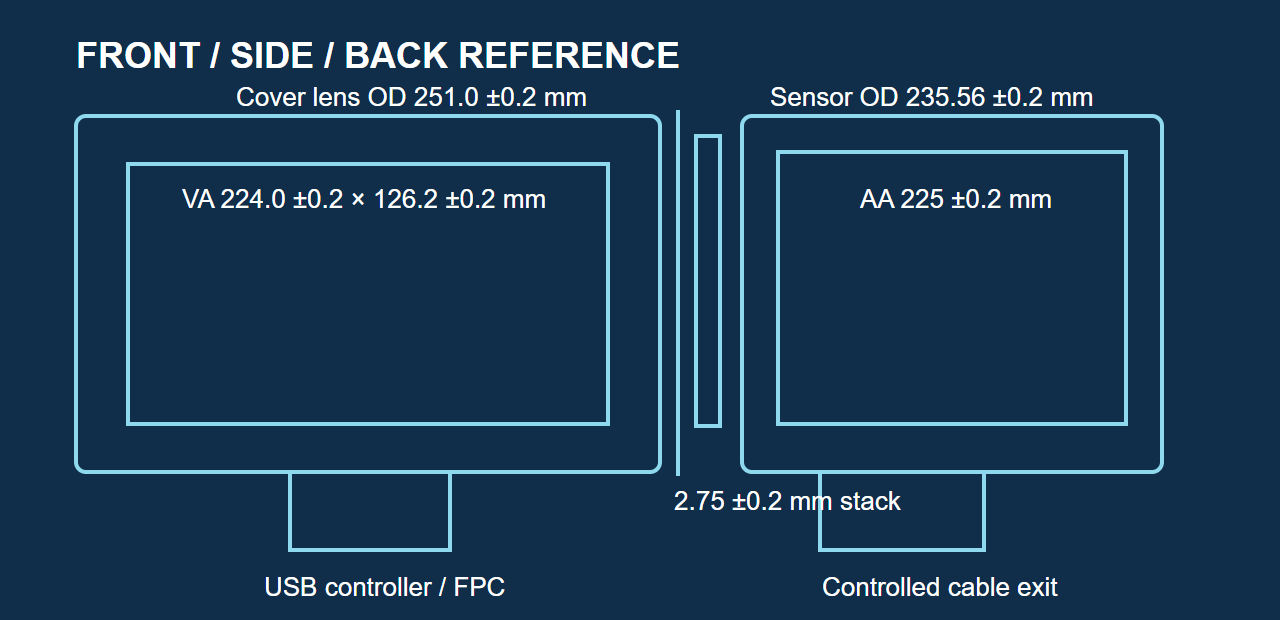
Geometry, controller & cable exit
The separate 10.1-inch PCAP drawing summary identifies cover geometry and controller/FPC positions. It is not the 15.6-inch module drawing.
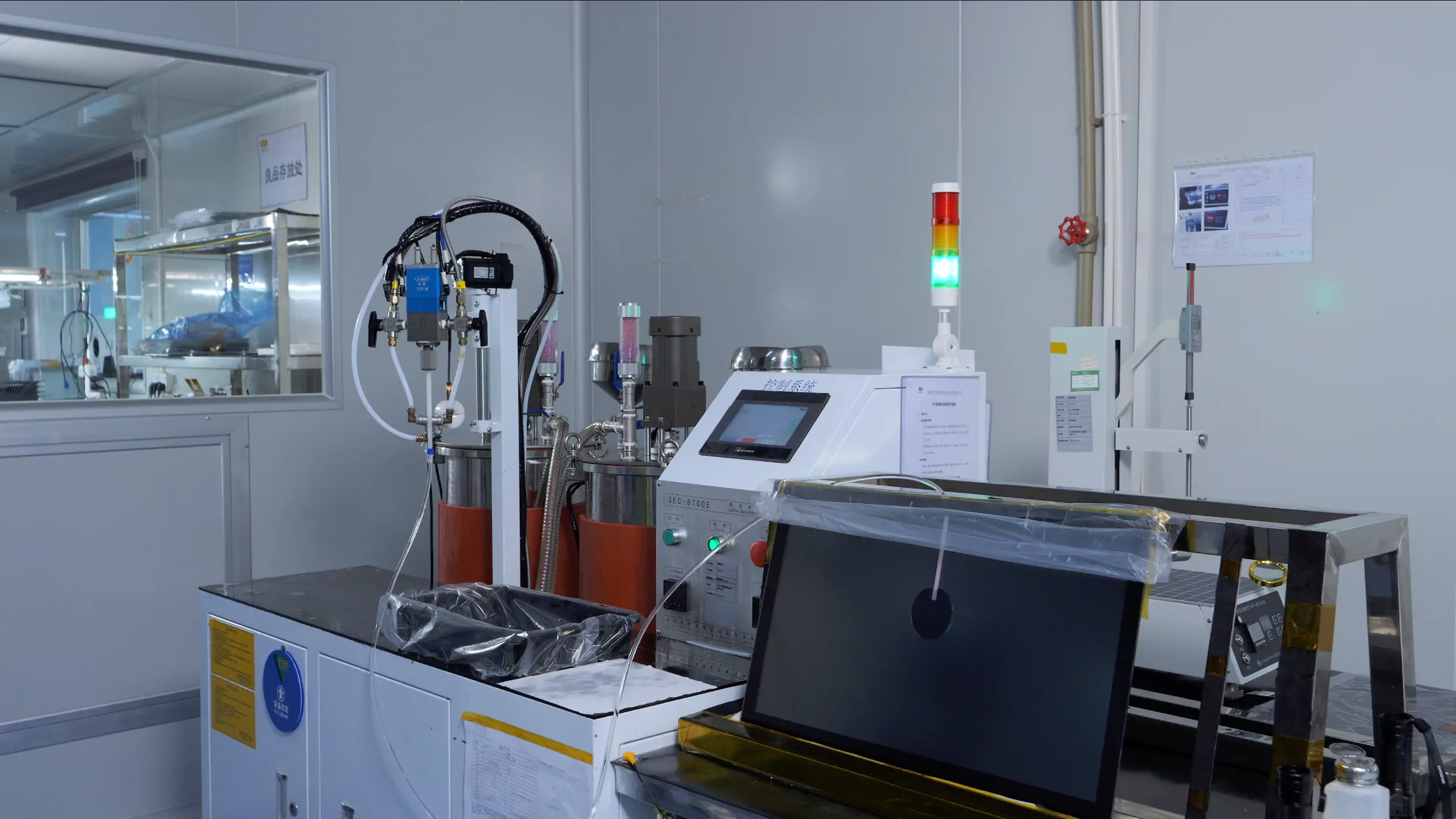
Optical-bonding production
Published manufacturing imagery shows bonding equipment. Bonding method, materials and acceptance criteria are defined for the selected stack.
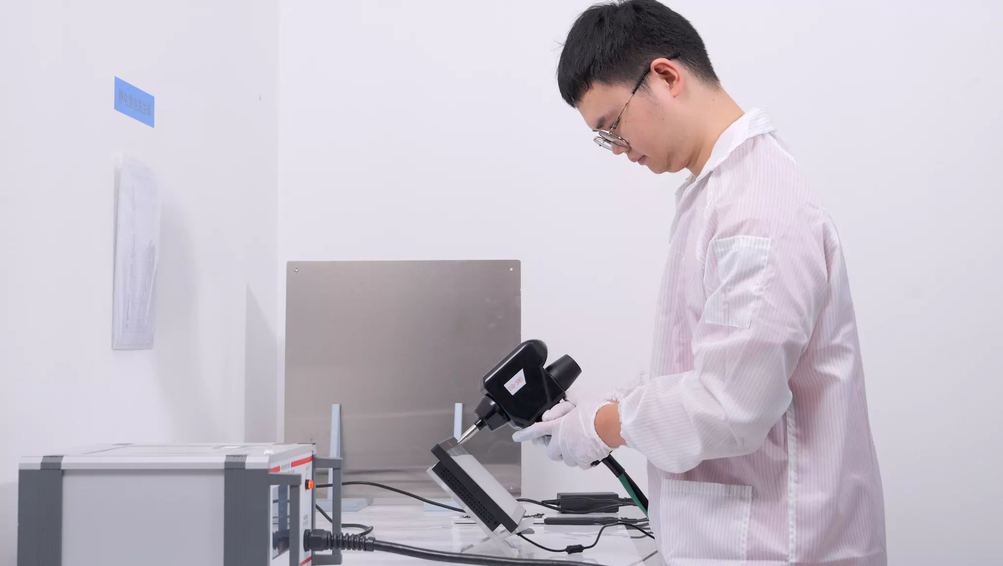
ESD & integration review
An internal check supports engineering evaluation of the tested setup. A product or vehicle compliance claim needs a matching scoped report.
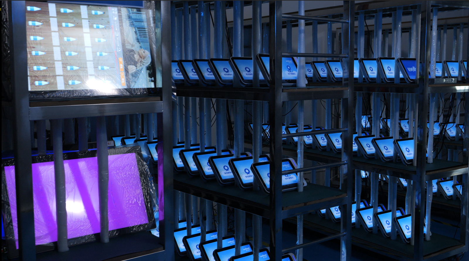
Powered aging capability
Equipment imagery shows an internal aging facility. Duration, operating conditions and release records belong to the agreed inspection plan.
Management-system certification and product test evidence have different scopes. Refer to Certifications & Compliance for the published records.
07 / Procurement questions
Before you specify
the hardware.
Practical answers for the drawing, sourcing and system-validation discussion.
Choose a PCAP panel when you already own the LCD and optical integration. A bonded module brings the touch sensor and selected LCD into a defined stack. A monitor adds an agreed assembly, video input, touch return, power and mounting arrangement for an external host. Share which parts are already fixed before comparing quotations.
Provide ambient light, viewing angle, target luminance, cover-glass finish and minimum dimming level. The LCD, reflection control, bonding, driver and enclosure heat budget need to be reviewed together. A high brightness number by itself is not proof that the installed display is readable in direct sunlight.
These are test conditions to define, not one universal capability. Supply the glove type and thickness, water exposure, actual cleaning agents and concentration, and the intended user actions. Controller settings, cover glass and the selected assembly need agreed checks. Chemical resistance and wet-touch behavior are separate evaluations.
No such approval is claimed here. Confirm the applicable edition, equipment category, installation and test boundary for standards such as EN 50155, IEC 61373, EN 50121-3-2, EN 45545-2 or ECE R10 with your compliance team. The correct model, configuration and report must match before any compliance claim is made.
State operating and storage limits separately, together with duty cycle, solar load, cooling and condensation. The LCD, adhesive, sensor, electronics and enclosure all need review. An IP rating applies to a defined tested boundary, including mounting, seals and enclosure; a bare touch panel or bonded module does not make the finished vehicle terminal IP65.
Separate the LCD/video interface from the touch connection. USB or I²C depends on the selected controller, host, OS and cable design. CAN, RS232/RS485 and wide-voltage vehicle power are not assumed for a PCAP panel or LCD module. Any monitor or Panel PC interface must be supported by its specific documentation and reviewed configuration.
Use the existing Contact Us form to describe the project and note that drawings are available. It has no file-upload field; request an agreed secure transfer method after initial contact. Include prototype/production quantities and program timing. Warranty, availability, change notification and validation responsibilities are confirmed in the quotation or supply agreement.
08 / Start the engineering conversation
Bring the installation.
Define the right assembly.
Request an application review for product selection, interface fit, mechanical integration and a sample-validation plan.
Transportation RFQ input checklist
Vehicle type, installation position, supply level, screen size, OD/VA/AA and drawing revision.
LCD/video interface, touch connection, OS, controller constraints, power source and cable routing.
Ambient light, dimming, glove/cleaning conditions, operating/storage temperatures, mounting, seals and shock/vibration targets.
EMC/approval targets, prototype and production quantities, program life and required timing.
Start with the existing form or email admin@evergloryltd.com. For drawings, request a secure transfer method after initial contact.