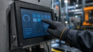
In touch screen manufacturing, the FPC is often exposed to stress during depaneling, assembly, connector insertion, bending and long-term device operation. A properly designed tear relief line helps reduce stress concentration, protect critical connection areas and improve both production yield and field reliability.
What Is an FPC Tear Relief Line?
An FPC tear relief line is a mechanical reinforcement design used around stress-sensitive areas of a flexible printed circuit. In touch screen applications, it is often added near connection points, forming edges, bending zones or the FPC root area to reduce the risk of tearing, cracking or conductor breakage.
The purpose is not to carry the main electrical signal, but to distribute mechanical stress more evenly. When the FPC is separated from a panel, bent during assembly, or pulled during device operation, the tear relief line helps prevent local stress concentration from propagating into critical signal traces.
Engineering principle: FPC tear protection should be designed together with copper layout, PI material, adhesive system, connector position, bending radius, stiffener design and final assembly method.
Why Tear Relief Design Matters in Touch Screen FPCs
Improve Depaneling Yield
During manual or mechanical depaneling, stress may concentrate around narrow connection points. Tear relief design helps protect these areas and reduce damage during separation.
Reduce Bending Failure
In devices that require repeated opening, folding, flipping or service access, a better stress distribution design can reduce the risk of FPC cracking or trace breakage.
Support Automated Assembly
In high-precision assembly for industrial equipment, automotive displays and smart devices, tear-resistant FPC design helps reduce handling damage and improves process consistency.
Key Design Guidelines for FPC Tear Relief Lines
The following values can be used as practical design references. Final dimensions should be confirmed according to FPC stack-up, copper thickness, line spacing, cutting method, tooling tolerance and reliability test requirements.
| Design Item | Typical Recommendation | Engineering Purpose |
|---|---|---|
| Line Width | Commonly designed at 0.15 mm or wider when layout space allows. | A line that is too narrow may not provide enough mechanical reinforcement; a line that is too wide may consume routing space. |
| Extension Length | Extend beyond the stress area on both sides, commonly 0.5 mm or more as a starting reference. | Helps cover the high-stress transition zone and prevent tearing from starting at the edge. |
| Distance from Forming or Cutting Line | Keep a controlled clearance from the forming line based on tooling tolerance and cutting accuracy. | Prevents the tear relief line from being damaged during punching, cutting or routing. |
| Spacing to Normal Traces | Maintain sufficient clearance from signal lines; spacing should follow electrical and manufacturing rules. | Reduces risk of short circuit, coupling, process defects or unwanted electrical interaction. |
| Connection to Ground Copper | If adjacent to ground copper, connection may be considered after electrical review. | Can improve mechanical continuity, but must not create signal interference or grounding side effects. |
Important: anti-tear structures should never be placed blindly. The design must avoid critical impedance areas, antenna zones, high-speed lines and sensitive touch signal paths unless reviewed by engineering.
Layout and Structure Recommendations
Place Tear Relief Lines on Stress-Sensitive Areas
Tear relief lines are most useful near the FPC root, connector transition area, depaneling bridge, bending zone and narrow neck area. These locations are more likely to suffer from pulling or bending stress.
Use Double-Side Reinforcement When Space Allows
For higher mechanical reliability, reinforcement can be considered on both sides of the FPC structure. This should be balanced with routing density, thickness and flexibility requirements.
Use Rounded Transitions
Sharp corners at the FPC root or connector area can create stress concentration. Rounded transition design and curved copper distribution help reduce the risk of crack initiation.
Avoid High-Impedance and Sensitive Signal Areas
Tear relief copper should not disturb antenna structures, impedance-controlled traces, touch sensing channels or other sensitive signal paths.
Practical recommendation: tear relief design should be reviewed together with the mechanical assembly drawing, not only the FPC Gerber layout.
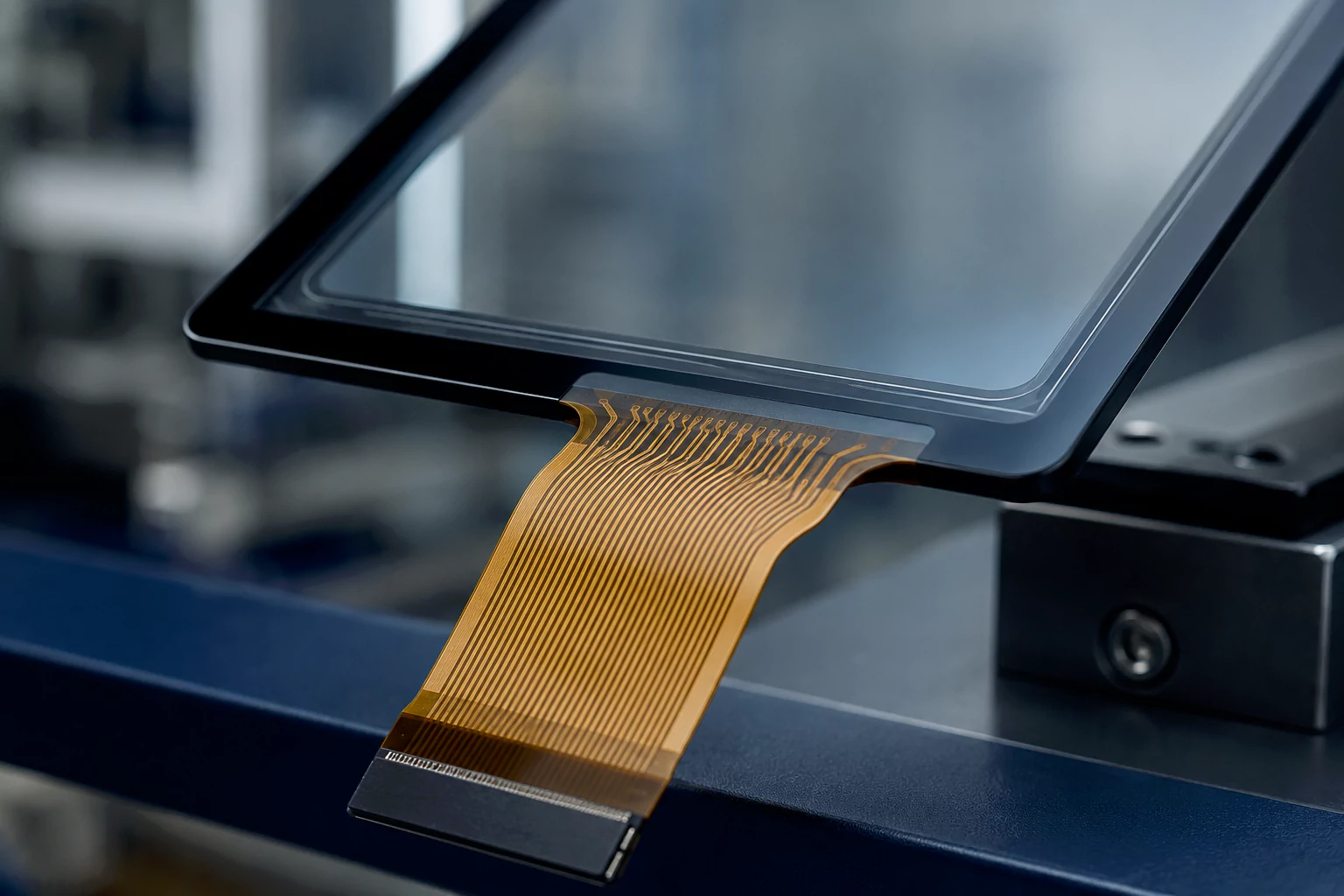
FPC Root Design: Rounded Transition and Tear Relief Line
The FPC root is one of the most stress-sensitive areas in a touch screen assembly. A clear local close-up view helps engineers and buyers understand how the rounded transition and tear relief line work together to reduce stress concentration during bending, depaneling and assembly handling.

What the Image Shows
- The FPC root area connected to a glass touch sensor.
- The rounded transition area at the FPC base.
- The tear relief line near the high-stress area.
- Stress direction cues that explain the tearing risk.
- A simplified side cross-section showing glass, ITO layer and FPC structure.
Why It Improves Engineering Clarity
FPC reliability is not only a material issue. It also depends on root geometry, copper distribution, stress direction, bend radius and assembly handling. A visual design reference makes these relationships easier to understand and supports better communication during design review.
Material and Process Considerations
| Item | Recommendation | Why It Matters |
|---|---|---|
| PI Base Material | Use suitable PI material based on bending, temperature and mechanical reliability requirements. | High-quality PI helps improve flexibility and long-term dimensional stability. |
| Copper Type | Rolled annealed copper is often preferred for dynamic bending; electro-deposited copper may be suitable for cost-sensitive or low-bending applications. | Copper fatigue behavior directly affects bending reliability and trace life. |
| Adhesive System | Choose adhesive or adhesiveless structure according to temperature, flexibility and delamination risk. | Poor adhesive selection can cause edge lifting, delamination or crack propagation. |
| Stiffener Design | Use stiffeners around connector areas when needed, but avoid creating sharp stress boundaries. | Stiffeners improve handling but may create new stress concentration if poorly designed. |
| Depaneling Method | Review punching, routing, laser cutting or manual separation method before finalizing tear relief geometry. | The cutting process determines the actual mechanical stress around the FPC edge. |
Common Risks in FPC Tear Relief Design
Reinforcement Too Weak
If the tear relief line is too narrow, too short or placed away from the stress point, it may not prevent tearing during depaneling or assembly.
Layout Space Conflict
Excessively wide reinforcement may reduce routing space, increase manufacturing difficulty or force critical signal lines into poor routing paths.
Unexpected Signal Impact
Copper added near sensing channels, antenna areas or high-impedance traces may affect electrical behavior if not reviewed carefully.
New Stress Concentration
A poorly shaped reinforcement structure may create a new rigid boundary and move the failure point to another area.
Important: FPC tearing is rarely solved by one line alone. The full solution should include layout, material, bend radius, connector support, stiffener design and assembly process control.
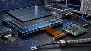
Reliability Validation for Touch Screen FPC Design
Before mass production, the anti-tear design should be verified under conditions close to the final application. The validation method should be selected according to whether the FPC is static, frequently bent, exposed to vibration, or handled during field service.
Depaneling Test
Check whether the connection area tears, cracks or deforms after the defined separation process.
Bending Test
Verify FPC performance under defined bend radius, bend angle and cycle count.
Continuity Test
Check whether signal lines remain electrically continuous after mechanical stress.
Assembly Simulation
Review pulling, connector insertion, cable routing and installed mechanical clearance.
Key point: validation data should be tied to the real FPC stack-up, bend condition, connector structure and final equipment assembly method.
everglory FPC Tear Relief Design Approach
everglory supports customized projected capacitive touch screens and touch display modules for industrial, automotive, medical, outdoor and embedded applications. For FPC reliability design, our engineering team reviews not only the FPC layout, but also the touch sensor structure, connector location, bending condition, assembly method and long-term reliability requirement.
FPC Layout Review
Review tear relief line width, placement, extension length, clearance, copper distribution and routing conflict.
Material Selection Support
Recommend PI, copper type, adhesive system and stiffener strategy based on static or dynamic bending requirements.
Reliability Validation
Support depaneling, bending, continuity and assembly simulation checks before mass production.
Recommended approach: use tear relief design together with rounded transitions, proper bend radius, controlled copper direction, suitable PI material and connector stress relief to improve overall FPC reliability.
Touch Screen FPC Tear Relief Design FAQ
Is a tear relief line required for every touch screen FPC?
Not always. It is most useful in stress-sensitive areas such as FPC roots, connector transitions, depaneling bridges and dynamic bending zones. The need should be evaluated based on structure and assembly conditions.
Can a tear relief line prevent all FPC breakage?
No. It helps reduce tearing risk, but FPC reliability also depends on bend radius, copper type, PI material, adhesive system, stiffener design, connector stress and assembly process.
Is rolled annealed copper always better than electro-deposited copper?
Rolled annealed copper is often preferred for dynamic bending because of better fatigue behavior. Electro-deposited copper may still be suitable for static or cost-sensitive applications after reliability validation.
Where should the tear relief line be placed?
It should be placed near the expected stress concentration area, such as the FPC root, bridge area, connector transition or bending zone, while avoiding sensitive signal paths and tooling damage areas.
Can everglory help optimize FPC tear-resistant design?
Yes. everglory can review the FPC layout, material selection, connector structure, bend condition and assembly process to recommend a more reliable tear relief design.
Need help improving touch screen FPC reliability?
Share your touch panel size, FPC drawing, connector location, bending condition, assembly method and failure symptoms. everglory can help review whether tear relief lines, rounded transitions, material upgrades or assembly changes are needed.