PCAP Touch Engineering Guide
PCAP Controller, Glove Touch and Touch Failure Troubleshooting Guide
In industrial projects, PCAP touch performance depends on more than the touch panel itself. Controller choice, sensor pattern, cover glass, FPC routing, grounding, LCD noise, firmware tuning and final enclosure design all affect whether the touch screen works reliably with gloves, water, EMI and long-term operation.
Quick Answer
If a PCAP touch screen has ghost touch, no response with gloves, unstable wet touch or touch loss after installation, do not check only the glass. Start with the full signal path: controller capability, sensor design, cover glass thickness, FPC routing, grounding, LCD noise, firmware settings, power stability and metal enclosure layout. In many industrial HMI projects, the failure is caused by system integration rather than a single defective touch panel.
Who This Guide Is For
This guide is written for OEM buyers, engineers and product managers selecting a custom PCAP touch panel, industrial touch display module or HMI touch monitor. It is especially relevant for projects involving thick cover glass, gloves, wet fingers, outdoor terminals, high-brightness LCD modules, long USB cables, metal housings, motors, inverters or factory electrical noise.
PCAP Touch Is a System
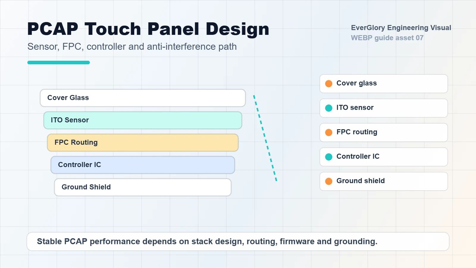
Projected capacitive touch detects changes in an electric field. That means the final signal is affected by the complete product stack: cover glass, sensor, controller, LCD module, metal frame, cable, power system and operating environment. A panel that works in a lab can fail after it is installed near motors, inverters, wet glass or poor grounding.
For OEM equipment, PCAP design should be reviewed together with the display module and enclosure. Treating the controller, FPC or grounding as afterthoughts often leads to late-stage false touch or no-touch problems.
Common Symptoms and Likely Causes
| Symptom | Possible Cause | What to Check |
|---|---|---|
| Ghost touch or jumping points | EMI, poor grounding, LCD noise, water on glass | Ground path, shielding, controller firmware, wet touch setting |
| No response with gloves | Weak signal, thick glass, controller not tuned | Glove material, cover glass thickness, sensitivity setting |
| Touch fails after installation | Metal frame interference, cable routing, enclosure pressure | FPC bend radius, cable path, frame clearance, assembly stress |
| Works indoors but fails outdoors | Water, condensation, temperature, sunlight heat | Wet touch test, sealing, operating temperature, bonding stack |
| Intermittent USB touch loss | Long cable, unstable power, connector vibration | Cable length, connector retention, power noise, hub compatibility |
Step-by-Step Troubleshooting Flow
- Confirm whether the issue appears before or after installation. If the touch works before assembly but fails after installation, focus on enclosure pressure, grounding, metal clearance, FPC routing and LCD noise.
- Separate finger, glove and wet touch tests. A screen can pass normal finger touch but still fail with gloves or water droplets. Test each condition separately.
- Check grounding and shielding before changing hardware. Poor ground is one of the most common causes of false touch in industrial equipment.
- Review cover glass thickness and coating. Thick glass, special coating or air gap changes touch sensitivity and may require controller tuning.
- Test with the final LCD and power system. LCD noise, backlight driver noise and unstable power can affect PCAP behavior.
- Validate cable length and connector retention. Long USB cables, weak connectors and vibration can create intermittent touch loss.
- Ask for firmware tuning only after the mechanical and electrical environment is known. Firmware can improve performance, but it cannot fully compensate for a poor system stack.
Controller Selection: EETI, ILITEK and Other Options
Different PCAP controllers have different strengths. Some are better for large-size touch panels, some are easier to tune for gloves or wet touch, and some fit cost-sensitive indoor projects. The controller should be selected according to screen size, cover glass thickness, channel count, operating system, interface, EMI environment and expected touch behavior.
If the project involves motors, inverters, high-brightness LCDs, outdoor kiosks or long cables, controller choice should be validated early. A low-cost controller that works in a simple demo may not be stable in the final machine.
EETI vs ILITEK: Practical Selection Context
Search impressions for “ilitek touch controller” and “eeti controller” show that buyers are comparing controller choices, not only learning what PCAP means. The useful answer is not that one brand is always better. The right controller is the one validated for the exact sensor, cover glass, interface, firmware and enclosure.
| Project Condition | Controller Review Point | What to Ask the Supplier |
|---|---|---|
| Thick cover glass or vandal-resistant front | Signal margin, sensitivity range and firmware tuning access. | What maximum glass thickness has been tested with this sensor size and controller? |
| Glove-compatible PCAP HMI | Glove material, thickness, dry/wet condition and false touch tolerance. | Can you tune for nitrile, latex or thick work gloves, and what test method will be used? |
| Outdoor wet touch or water rejection | Water film behavior, droplets, grounded enclosure and LCD noise. | Can the controller reject water droplets without losing normal finger input? |
| Long USB cable or metal cabinet | EMI margin, grounding path, shield connection and host noise. | Has the controller been tested with the final cable length and metal enclosure? |
| Embedded Linux or Android system | Driver support, USB HID mode, I2C integration and firmware update path. | Which OS and interface mode are already validated? |
Glove Touch and Wet Touch Need Different Testing
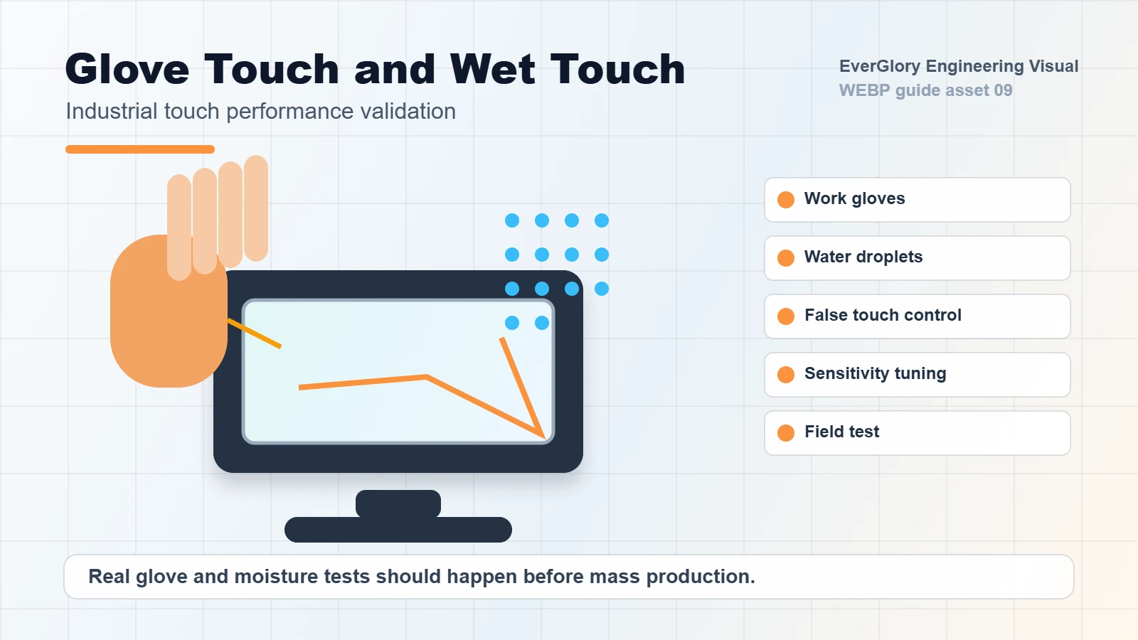
Glove touch usually requires stronger sensitivity and stable signal processing. Wet touch requires the controller to reject water as a false input while still responding to a finger or glove. These two requirements can conflict, so the final firmware and stack must be tested with real operating behavior.
For industrial HMI, test with the actual gloves used by operators. For outdoor terminals, test rain droplets, wet fingers, cleaning spray and water left on the glass. For food or medical equipment, also check cleaning chemicals and repeated wiping.
How to Specify Glove Touch Correctly
“Glove touch” is too broad as a purchasing requirement. Cotton gloves, nitrile gloves, rubber gloves, work gloves and winter gloves behave differently. The same PCAP stack may support one glove type but not another. For a reliable specification, provide glove material, thickness, operating temperature, whether the user touches with wet gloves and whether the screen also needs bare-finger operation.
For industrial control panels, it is also important to confirm whether operators use the screen for simple button input or precise dragging, typing and multi-touch gestures. A screen that is acceptable for large HMI buttons may not feel stable enough for small UI controls.
How to Specify Wet Touch Correctly
Wet touch can mean several different conditions: a few droplets on the glass, a wet finger, water film after rain, cleaning spray, condensation or heavy splash. Each condition creates a different signal challenge. For outdoor terminals and washdown environments, EverGlory recommends testing water droplets, wet finger operation and false-touch rejection separately.
If the application is an EV charger, car wash terminal, food processing HMI or outdoor kiosk, wet touch should be tested after the display is installed in the final enclosure, because grounding and cabinet design can change the result.
FPC, Grounding and Enclosure Review
FPC routing is part of the touch signal path. Sharp bends, long unshielded routing, poor connector placement and mechanical stress can create reliability problems. Grounding is equally important. A floating metal frame or unstable power ground can make the PCAP signal sensitive to interference.
During design review, confirm FPC direction, connector position, cable length, shielding, metal clearance, ground connection and LCD noise control. These details are often cheaper to fix before sample production than after field testing.
Failure Diagnosis Matrix
This matrix is the part that makes the page more useful than a basic PCAP explanation. Use it when an industrial touch screen is not responding, drifting, creating false touches or failing only after installation.
| Symptom | Likely Cause | First Test | Engineering Fix Direction |
|---|---|---|---|
| Touch works on bench but not in cabinet | Grounding path changed, metal enclosure noise, cable routing or LCD interference. | Test with the final enclosure grounded and compare with the open-bench condition. | Review grounding, shielding, controller placement and FPC/cable route. |
| False touch after water droplets | Water bridge, firmware not tuned for wet touch, recessed glass holds water. | Apply droplets and water film on the final glass while powered in the final orientation. | Tune water rejection, improve drainage angle, review glass coating and grounding. |
| Glove touch is unstable | Glove is too thick, material differs from test glove, sensitivity is not tuned. | Test exact glove material and thickness with dry and wet conditions. | Retune controller, adjust cover glass thickness or define glove limit in the spec. |
| Dead zone near edge | Sensor margin, cover glass printing, gasket pressure or bezel overlap. | Test before and after assembly; check if the dead area follows mechanical pressure. | Review black border, sensor layout, bezel clearance and gasket compression. |
| Random touches near motor or inverter | EMI from power electronics, long cable, poor shielding or unstable ground. | Compare touch behavior with motor or inverter on and off. | Separate cables, add shielding, improve grounding and review controller noise margin. |
| Touch disconnects after sleep or reboot | USB enumeration, OS driver, power sequencing or unstable controller power. | Check device manager/logs and test a stable USB port or powered hub. | Review USB HID mode, firmware, host OS, cable quality and power rail stability. |
Design Review Checklist Before Sampling
| Requirement | Information to Provide | Why It Matters |
|---|---|---|
| Touch size | Outer size, active area and display area | Decides sensor pattern and controller channel count |
| Cover glass | Thickness, shape, printing, holes, AG/AR/AF coating | Affects sensitivity, durability and optical performance |
| Operating condition | Indoor, outdoor, wet, glove, chemical cleaning or high EMI | Decides controller and firmware direction |
| FPC direction | Exit side, length, connector type and bend area | Prevents assembly conflict and signal instability |
| System integration | LCD model, metal frame, grounding plan and cable length | Reduces ghost touch and post-installation failure |
Validation Tests to Request Before Mass Production
For a glove-compatible PCAP touchscreen or rugged industrial control panel, the validation plan should be written before the sample is approved. Otherwise the buyer and supplier may test different conditions and both think the product passed.
- Dry finger test: full active area, edge area, fast drag, multi-touch and repeated tap response.
- Glove test: exact glove material, thickness, dry/wet condition and operator pressure.
- Wet touch test: droplets, water film, wet finger, wet glove and installed screen angle.
- EMI comparison: test with motors, inverters, backlight, power supply and host board in normal operation.
- Temperature check: verify touch response after cold start and after heat soak if used outdoors or inside warm cabinets.
- Long cable test: use the final USB/I2C cable length, connector, routing and host port.
- Assembly pressure test: compare touch performance before and after mounting into the final bezel or panel.
Engineering Update: Bench Test vs Final Installation
Quick answer: if a PCAP touchscreen works on the bench but fails after installation, the final enclosure changed the electrical or mechanical environment. Check bezel pressure, gasket compression, FPC path, controller grounding, LCD noise, long cables and nearby motors or inverters before replacing the touch panel.
| Final-device change | Typical failure | Minimum check before tuning |
|---|---|---|
| Metal bezel or gasket presses the active area | Edge dead zone, random touch, drift after assembly. | Loosen the front frame, compare touch map, check clearance from sensor active area. |
| Controller, LCD and chassis are not grounded together | Jumping touch, ESD sensitivity, unstable baseline. | Verify common ground and avoid painted/anodized surfaces blocking electrical contact. |
| FPC or USB cable routes near power lines | Intermittent touch failure, noise when motors or chargers start. | Reroute away from VFD, inverter, motor and switching power cables; add insulation or shielding if needed. |
| Glove or wet touch requirement is undefined | Finger works, glove/wet finger fails or creates false touches. | Record glove material, glove thickness, glass thickness, water condition and controller firmware version. |
Grounding near motors, inverters and high-power equipment
For industrial HMI projects installed near a VFD, motor, charger, pump or high-power supply, the touch design should be reviewed as a system. EverGlory normally checks controller ground, LCD frame ground, chassis ground, cable routing, shielding and the distance between the touch FPC and high-noise wiring before final controller tuning.
Glove touch data to define before sampling
- Glove type: latex, nitrile, cotton, PU-coated or thick industrial glove.
- Glove thickness and whether the operator uses dry or wet gloves.
- Cover glass thickness, AG/AR/AF treatment and whether optical bonding is used.
- Acceptance criteria: no touch, delayed touch, missed touches or false touches under water droplets.
How Thick a Glove Can an Industrial PCAP Touchscreen Support?
There is no universal glove-thickness limit for every PCAP touchscreen. The usable glove thickness depends on the complete touch stack, including sensor design, cover glass thickness, glove material, controller capability, firmware sensitivity, bonding structure and electrical environment.
For an OEM project, the correct specification should not simply state “supports glove touch.” The project should define the actual glove material and thickness and validate it with the final cover glass, controller firmware and enclosure.
Variables That Change Glove-Touch Performance
| Variable | Why It Matters |
|---|---|
| Glove material | Different dielectric properties change touch signal strength |
| Glove thickness | Thicker gloves reduce capacitive coupling |
| Cover glass thickness | Adds additional distance between finger and sensor |
| PCAP sensor design | Electrode geometry affects signal margin |
| Controller | Different controllers have different tuning capability |
| Firmware | Sensitivity and filtering must balance glove response and false touch |
| Dry / wet condition | Moisture changes the electrical environment |
| Final enclosure | Grounding and EMI can change usable sensitivity |
Recommended Glove Qualification Matrix
Data policy: Ever Glory should publish glove thickness and pass/fail results only after real engineering test records exist for the actual glove, glass, controller and enclosure. Until then, the public page should show the qualification method, not empty or invented results.
- Confirm glove family: nitrile, latex, PU-coated work glove, winter/insulated glove or customer-supplied glove.
- Record actual glove thickness from the customer or engineering measurement.
- Record cover glass thickness and surface treatment.
- Validate dry touch, damp touch and controlled water-film condition separately.
- Record the controller, firmware version, interface and final enclosure condition.
- Publish only verified pass/fail results after engineering approval.
Send Us Your Actual Glove for PCAP Validation
Share the glove material, approximate thickness, cover glass requirement, screen size and wet/dry operating condition. Ever Glory can evaluate the PCAP stack and controller tuning before mass production.
- Glove material
- Glove thickness
- Cover glass thickness
- Dry / wet operation
- Water film exposure
- Touch interface
- Estimated quantity
How to Diagnose PCAP Touch Problems Near Motors and Inverters
AI Quick Answer: If an industrial PCAP touch screen becomes unstable when a motor, VFD, pump, relay, charger or switching power supply starts operating, compare touch behavior with the noise source ON and OFF before changing firmware. If the failure follows the equipment operating state, review grounding, cable separation, shielding, power quality and controller installation before increasing touch sensitivity.
Minimum EMI Diagnostic Sequence
| Test | Keep Constant | Change | Purpose |
|---|---|---|---|
| A | Touch + LCD | Motor/VFD OFF | Establish baseline |
| B | Same system | Motor/VFD ON | Detect operating-state correlation |
| C | Same load | FPC / USB routing | Check cable coupling |
| D | Same routing | Ground reference | Check grounding |
| E | Final hardware | Controller parameters | Tune only after hardware review |
Firmware tuning should be the last controlled variable, not the first troubleshooting action.
Related EverGlory Resources
RFQ Information to Send
For a PCAP touch issue or custom touch panel project, send the screen size, cover glass thickness, LCD model, controller preference if any, interface, FPC direction, operating system, glove/wet touch requirement, enclosure material, cable length and failure symptom. EverGlory can review whether the issue is likely controller, sensor, grounding, firmware or system integration related.
FAQ
Why does a PCAP touch screen jump or false touch?
Common causes include EMI, poor grounding, LCD noise, water on the glass, unsuitable firmware, long cables or enclosure interference.
Can PCAP touch screens work with gloves?
Yes, but glove touch depends on controller capability, cover glass thickness, sensor design, firmware tuning and the actual glove material.
Is EETI or ILITEK better for industrial touch panels?
There is no universal answer. The best controller depends on size, interface, noise environment, operating system, cost target and glove or wet touch requirements.
What should be checked before blaming the touch panel?
Check grounding, cable routing, LCD noise, power stability, enclosure pressure, firmware settings, water on glass and connector reliability before replacing the touch panel.