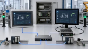
A system-level method for separating ground functions, controlling high-frequency return paths, protecting the touch front end from ESD, and diagnosing interference in the final assembly.
Quick answer: how should a PCAP touchscreen be grounded?
A projected-capacitive touchscreen should be integrated with clearly defined protective-earth, chassis, signal-return, and shield functions. The controller needs a continuous reference and a compact return path; the enclosure needs a controlled potential and an ESD route; high-current and high-di/dt loops should not share narrow return segments with the touch analog front end.
Grounding can solve some common-mode, enclosure-potential, and discharge-path problems. It cannot correct an unsuitable sensor pattern, excessive metal overlap, poor power integrity, an electrically noisy LCD, mechanical pressure, or incorrect controller tuning. Treat the PCAP panel, LCD, controller, power supply, cables, and enclosure as one system.
Separate the four ground-related functions first
The controller detects very small changes in mutual or self capacitance. Power ripple, common-mode voltage, enclosure potential, or ESD current entering the same reference path can raise the channel-noise floor and appear as coordinate drift, false touch, touch dropout, or weak edge response.
| Function | Primary purpose | PCAP integration concern |
|---|---|---|
| Protective earth (PE) | Electrical safety for equipment that requires protective earthing. | PE requirements follow the equipment class and applicable safety standard. A Class II product may have no PE terminal; that alone does not indicate an incorrect touch design. |
| Chassis ground | Controls exposed metal, shields, and ESD current paths. | Its relationship to PE and signal return must be intentional. Random contact through screws, paint, or conductive foam creates variable behavior. |
| Signal / power return | Provides the reference for the touch controller and digital interface. | Continuity, return-loop area, shared impedance, and connector geometry matter more than a simple continuity reading. |
| Shield / guard | Modifies electric-field coupling around sensing nodes. | A grounded shield, driven shield, and guard electrode are different functions. Use only the topology supported by the selected sensor and controller. |
Design the PCB and FPC for low high-frequency impedance
A low DC resistance is not the same as a low impedance at the touch scan frequency or at ESD/EMC frequencies. A long wire, a large loop, a narrow shared return, or an inconsistent chassis bond can measure as “connected” with a multimeter and still generate substantial reference movement.
Controller placement
Place the controller close to the sensor or FPC exit. Keep electrode trace length, spacing, and parasitic loading inside the controller and sensor supplier’s design limits.
Return continuity
Provide a continuous reference plane and a controlled power return. Avoid forcing touch return current through motor, relay, backlight-converter, or other high-current paths.
Noise-source separation
Keep touch FPC and high-impedance sensing nodes away from LCD source/clock routing, VCOM-related nodes, backlight DC/DC switching loops, motors, relays, radios, and high-current conductors.
Controlled crossing
Where separation is impossible, prefer a near-orthogonal crossing and minimize parallel overlap. Define the cable position so production units cannot drift toward the noise source.
Do not add grounded copper between sensing channels merely to “isolate” them. A fixed ground conductor may load the channel or distort edge fields. Likewise, ferrites, common-mode chokes, RC networks, and TVS devices must be chosen for the interface bandwidth, current, impedance profile, and protection target—not applied as universal touch fixes.
Route ESD current around the touch analog front end
A robust design encourages discharge current to enter the chassis or a dedicated protection path before it can couple into the sensor electrodes, FPC, connector, or controller analog front end.
- Control clearances and seams around exposed metal so a discharge cannot jump unpredictably to the FPC or connector.
- Place interface TVS protection close to the external energy entry point, with a short and wide discharge return.
- Use defined chassis bonds, insulating barriers, shielding, and structural current diversion as a coordinated design.
- Confirm whether an edge shield, shield film, driven shield, or guard is supported by the controller architecture before adding it.
- Specify the required performance criterion during and after ESD: normal operation, self-recovery, permitted reset, and absence of permanent degradation are not interchangeable outcomes.
Insulating tape may prevent accidental contact, but it does not replace required creepage and clearance, connector retention, structural fixation, or a verified discharge path.
Diagnose interference with controlled comparisons
Reproduce the failure in the final device configuration before adding ground wires. Change one variable at a time and record controller raw counts, baseline, peak-to-peak noise, touch signal, and the exact condition that triggers the fault.
| Observed symptom | First checks | Useful evidence |
|---|---|---|
| False touches appear after connecting the adapter | Adapter common-mode noise; USB/power-cable return; chassis-to-signal relationship. | Compare an approved low-noise adapter; measure ripple/common-mode behavior; correlate the change with channel raw data. |
| Touch becomes unstable while holding the metal enclosure | Floating chassis; bezel geometry; body coupling; enclosure bond and ESD path. | Compare an insulated chassis with a controlled bond while keeping LCD, power, firmware, and cable position unchanged. |
| Noise correlates with LCD refresh or image content | LCD clock/source lines; VCOM or panel supplies; backlight PWM; FPC overlap. | Change test pattern, refresh rate, and brightness; determine whether channel noise follows a timing state. |
| Only the edge loses touch | Edge-electrode loading; metal/adhesive overlap; gasket pressure; edge compensation. | Compare bare module and final assembly; review edge-channel baseline, touch signal, SNR, and mechanical tolerance. |
If a temporary bond changes the symptom, that is evidence about a coupling path—not proof that the temporary wire is a production solution. Confirm safety, EMC, durability, and manufacturing repeatability before freezing the change.
Validation and production-release requirements
- Test the full active area with the final LCD, cover glass, bezel, cables, adapter, controller configuration, and host software.
- Cover power-up, standby/wake, maximum system load, relevant display patterns and refresh rates, charging, human grip, and rated environmental conditions.
- Run applicable ESD, EFT, radiated-RF, and conducted-RF immunity methods with predefined performance criteria.
- Derive ground-bond acceptance from the safety design, EMC architecture, drawing, and a defined measurement path; do not use an unexplained universal “1 Ω” rule.
- Freeze the topology, bond material, fastener torque, conductive-foam compression, cable position, and controller parameters in controlled documentation.
Standards and evidence boundary
IEC 62368-1 may be relevant to AV/ICT equipment safety depending on product scope. IEC 61000-4-2, -4-3, -4-4, and -4-6 define commonly used immunity test methods. The applicable editions, test levels, setup, and performance criteria must come from the target product standard, customer requirement, and compliance plan. The controller, sensor, connector, and protection-device supplier documents remain project-specific design inputs.
PCAP grounding engineering FAQ
Should the PCAP controller ground be connected directly to the metal bezel?
Not by default. The correct connection depends on the controller reference design, chassis architecture, PE strategy, bezel distance, ESD path, and measured channel loading. Compare defined isolated and bonded conditions before selecting the production topology.
Why does adding a ground wire sometimes improve a bench test but fail in production?
The temporary wire may change common-mode impedance, loop area, or chassis potential without controlling location, length, contact resistance, or durability. Production requires a documented bond and verification across worst-case assembly, adapters, temperature, and EMC conditions.
Is continuity testing enough to approve a grounding design?
No. Continuity is useful for workmanship, but it does not characterize high-frequency impedance, shared return paths, resonances, or discharge-current flow. Combine it with raw touch data, power and EMC measurements, and final-device functional testing.
Need a PCAP integration review?
Share the sensor and LCD drawings, controller/FPC layout, enclosure material, power architecture, interface, and failure conditions. EverGlory can review the touch stack and define a focused sample-validation plan.
Discuss Your ProjectView Custom PCAP Panels