
Outdoor display integration workflow
Outdoor EV Charger Touch Display Engineering Example
Define the enclosure, optical path, thermal load, wet-touch conditions and electrical environment before building an outdoor charger display sample. This example turns those conditions into reviewable engineering gates.
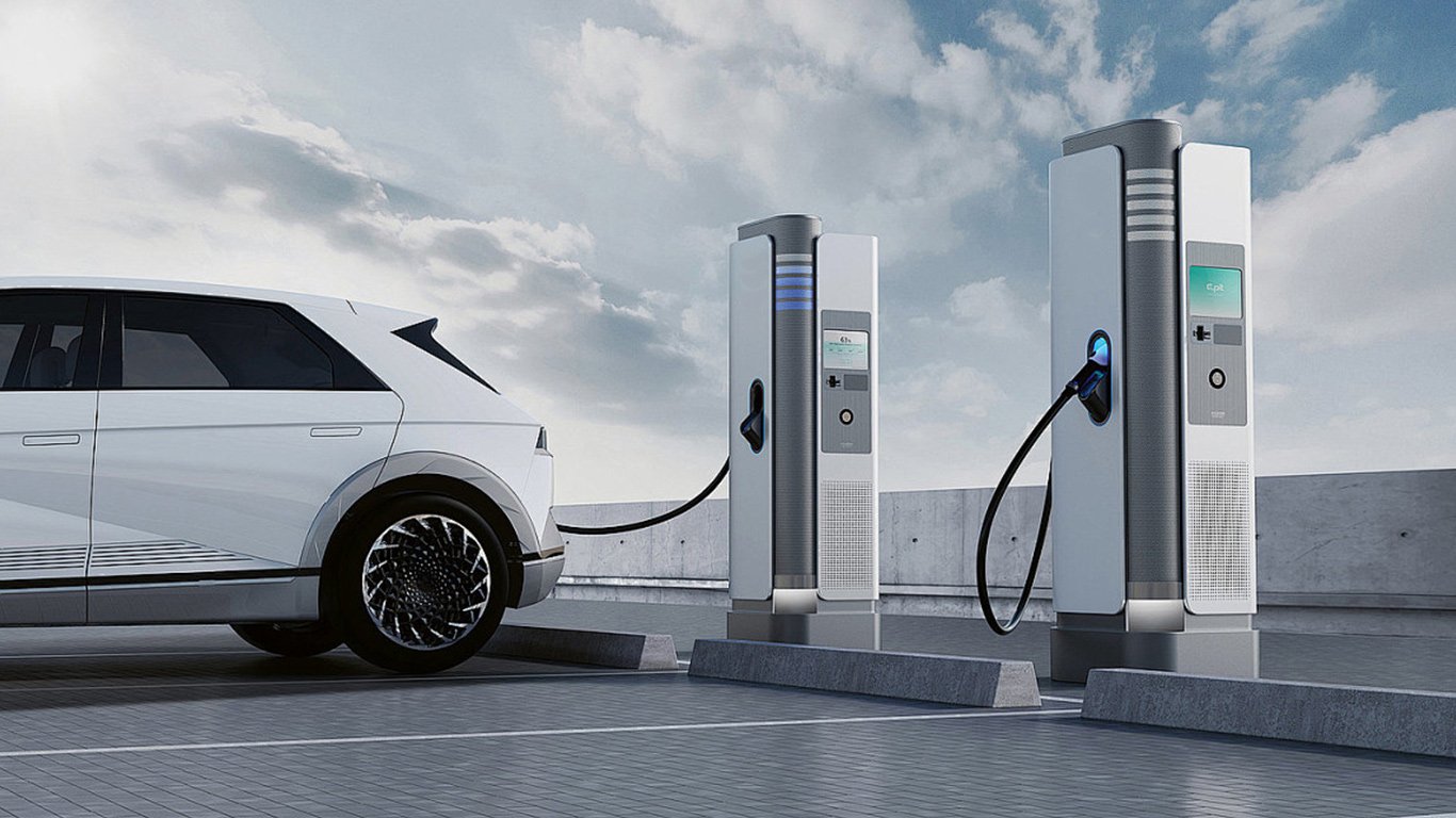
Design drivers
Outdoor performance is a system decision
Optical readability
Define ambient-light exposure, brightness target, cover-glass treatment, bonding approach and acceptable visual contrast.
Sealing boundary
Identify which interface is expected to resist water or dust and how the gasket, mounting surface and enclosure complete that boundary.
Thermal and UV exposure
Review sun load, internal heat, ventilation, material aging and temperature distribution instead of relying on an LCD temperature line alone.
Touch behavior
Specify water-film conditions, droplet rejection, glove type, cover-glass stack and grounding before controller tuning.
Electrical environment
Assess charger power electronics, cable routing, grounding and controller behavior as part of EMC engineering.
Service and lifecycle
Plan access, replaceable parts, display availability, configuration records and change notification.
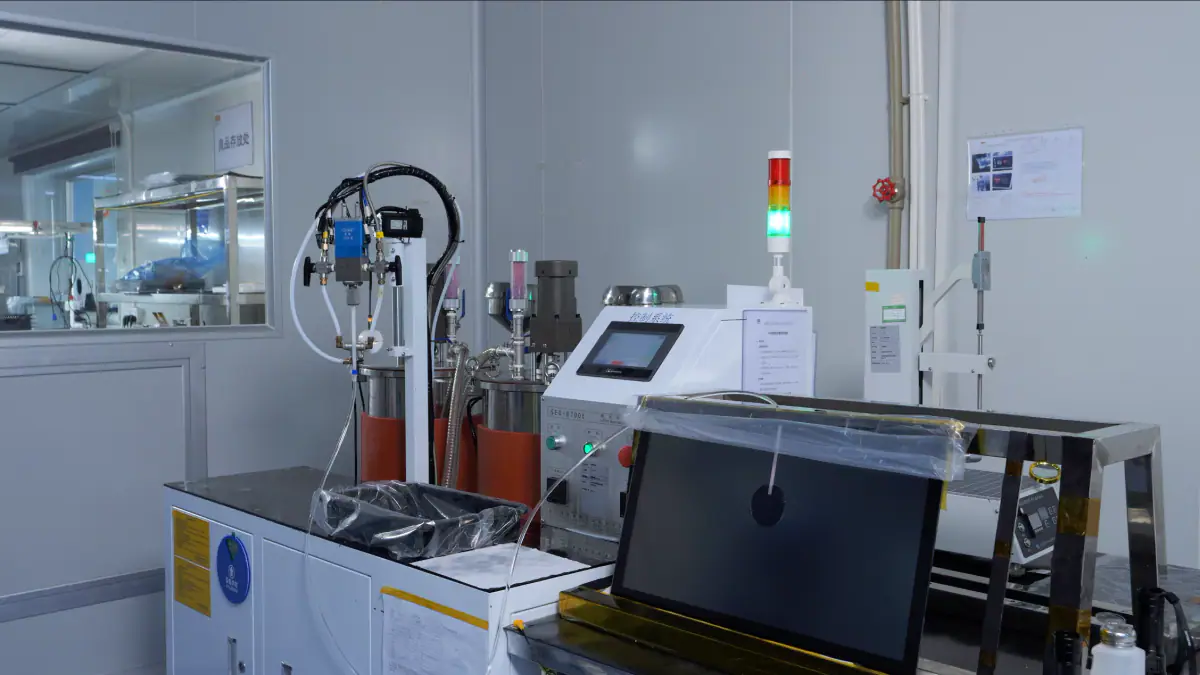
Sample definition
Conditions must be recorded before performance is discussed
- Installed orientation and viewing angle
- Ambient-light and readability target
- Front-seal boundary and enclosure details
- Operating and storage temperature targets
- Wet-touch and glove-use conditions
- Power, display and touch interfaces
- Required third-party standards or buyer acceptance methods
Qualification boundary: the final EV charger manufacturer remains responsible for system-level safety, EMC, ingress protection and market compliance.
Decision gates
Engineering path for an outdoor sample
Environment
Define light, water, dust, temperature and vandal exposure.
Optics
Select brightness, coatings and bonding approach.
Mechanics
Confirm glass, gasket, mounting and enclosure boundary.
Electronics
Review power, I/O, cable routing and grounding.
Sample
Build and evaluate the defined configuration.
Release
Record results, changes and remaining system responsibilities.
Common engineering questions
Frequently asked questions
Is 1,000 or 1,500 nits always required?
No. Brightness is selected with ambient light, optical reflections, viewing angle, thermal load, power budget and enclosure conditions. A target value must be validated in the intended installation.
Does a sealed front automatically make the complete charger IP rated?
No. The system rating depends on the full enclosure, gasket, mounting surface, fasteners, connectors and tested boundary. A component front-seal target cannot be extended to the complete charger without evidence.
Does optical bonding solve every outdoor problem?
No. It can reduce internal reflections and improve mechanical coupling, but thermal design, UV exposure, cover-glass treatment, condensation risk and service requirements still need separate evaluation.
Define the outdoor conditions before sample build
Send the enclosure drawing, orientation, sunlight exposure, brightness target, sealing boundary, temperature range, touch conditions, power and interfaces. EverGlory will identify the open engineering decisions.
Related evidence
Continue the outdoor engineering review
Connect the example to an outdoor configuration, evidence plan and controlled production path.
Outdoor touch solutions
Review optics, sealing, touch behavior and thermal inputs.
Outdoor touch monitors
See a relevant monitor family and define the required configuration.
Quality and testing
Specify conditions and acceptance limits before sampling.
Compliance evidence
Request only the records that match the quoted product.