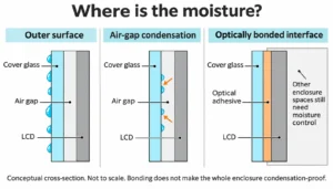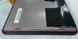
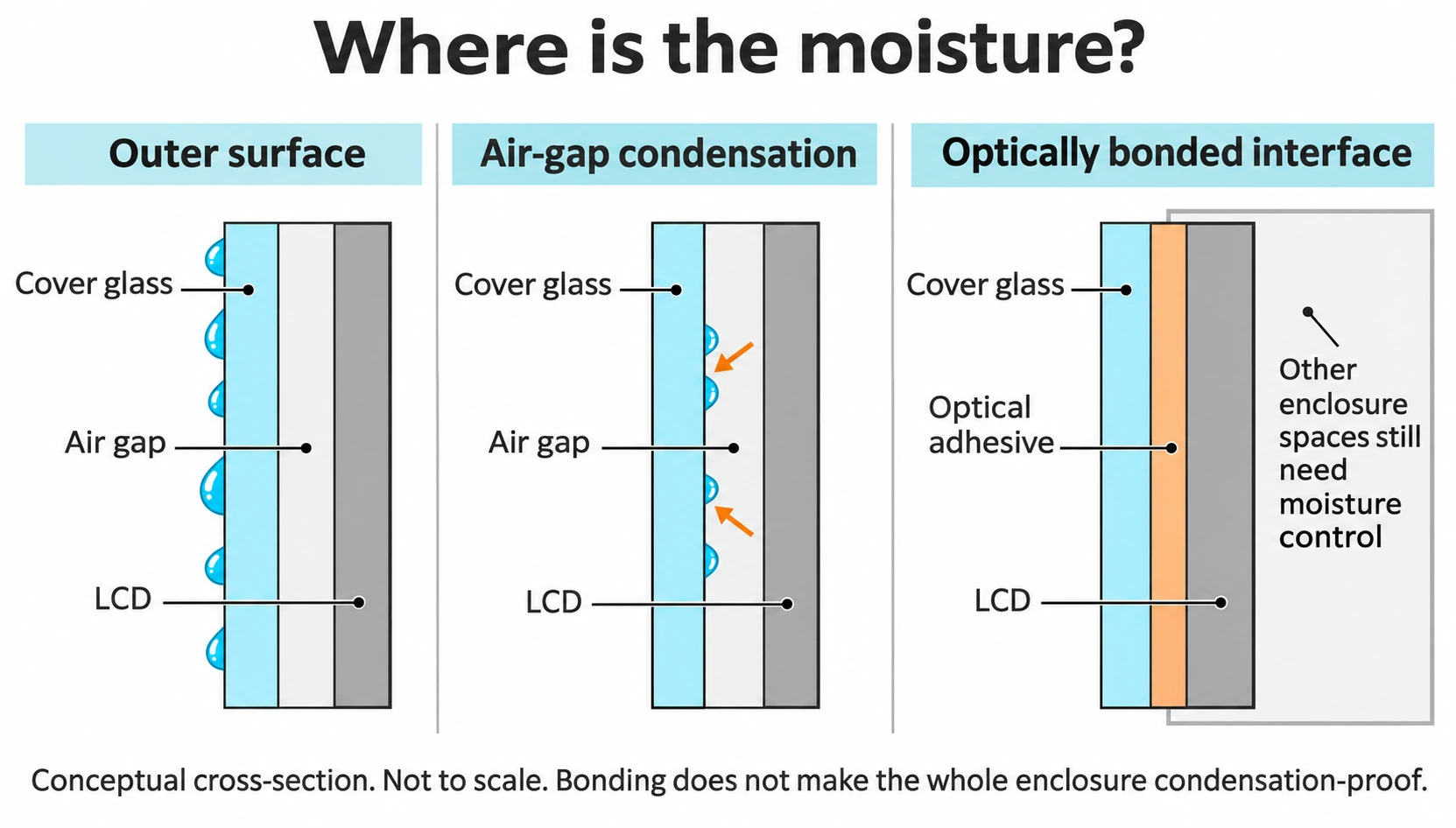
Touch display condensation occurs when a surface becomes cold enough for moisture in the surrounding air to collect on it. In an air-bonded assembly, the space between the touch panel and LCD is one possible location. First distinguish external water, internal fogging and a persistent optical defect. Then review the moisture path, sealing, temperature changes and assembly condition. Optical bonding removes the selected air gap; it does not make every space in the enclosure condensation-proof.
A display can resist external water at a defined boundary and still have a condensation problem. Treat the optical stack and the equipment enclosure as connected design questions. This guide focuses on locating and diagnosing fogging in an air-bonded touch display, rather than selecting a waterproof label.
Locate the moisture before choosing a remedy
Photograph the symptom before wiping or warming the display. Note whether it appears on the accessible outer surface, behind the cover glass, or in another part of the assembly. Record when it starts, how it changes and whether it clears under normal, approved operating conditions.
The opening illustration compares the affected spaces. View the full-resolution layer diagram. It is a conceptual drawing, not a product drawing or test result; removing one air gap does not control moisture throughout the enclosure.
| What you observe | Possible location | What to check next |
|---|---|---|
| The mark clears when the outer glass is wiped using an approved method. | External water or surface contamination | Weather exposure, cleaning, drainage and wet-touch behavior |
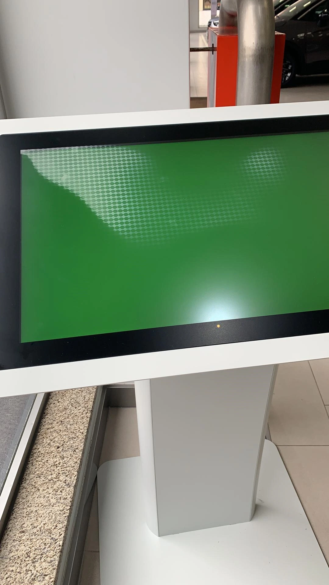
| The outer surface is dry, but fog is visible behind it and changes with temperature. | An internal air space, including the TP/LCD gap | Assembly stack, humidity history, sealing and the temperature transition |
| Water is visible near rear connectors or inside the housing. | Enclosure ingress or condensation outside the optical gap | The actual ingress boundary and internal moisture paths; isolate power if liquid threatens electronics. |
| A white patch, bubble or edge boundary remains after conditions stabilize. | Potential residue, coating damage or a bonding/display defect | Optical inspection and supplier review; do not assume the mark is removable moisture. |
These observations help organize the investigation. They are not a diagnosis from appearance alone. For example, a visible pattern behind the glass can need both a humidity review and inspection of the display stack.
Trace the temperature change and moisture path
Condensation depends on the local surface temperature and the moisture content of the air next to it. Ambient temperature alone is not enough. A cold front surface can meet warmer, humid air after equipment is moved, powered down or exposed to a change in weather or airflow.
Look for a repeatable sequence: storage or idle period, startup, cooling, cleaning or a day/night transition. Record ambient temperature and relative humidity, relevant surface temperatures where they can be measured safely, and the equipment’s operating state. Compare those measurements with the onset and clearing of the fog.
Review assembly history as well as field conditions
Moisture may be present when the assembly is closed, enter through a damaged or incomplete boundary, or move through materials over time. Review the bonding perimeter, joints, cable penetrations and the handling of parts before sealing. An apparent gap-free bead in a photograph does not prove that the complete assembly meets its sealing requirement.
Keep ingress protection and condensation control separate
An ingress rating describes the tested protection under its specified conditions. It is not a blanket promise against condensation throughout a temperature cycle. The waterproof monitor integration guide explains why the front panel, rear housing, connectors and final installation need to be considered separately.
Likewise, an anti-fingerprint surface treatment can affect water behavior on the exposed glass, but it does not remove moisture from an internal cavity. Do not substitute a coating claim for a review of the air space.
Select the remedy for the affected space
| Design option | What it can address | What still needs review |
|---|---|---|
| Correct the existing sealing or bonding perimeter | Identified discontinuities or defects at the intended boundary | Trapped moisture, material compatibility, enclosure paths and repeatable assembly |
| Control moisture during assembly and storage | Moisture introduced before closure or during handling | Conditions after installation and the long-term behavior of the completed enclosure |
| Use optical bonding at the specified TP/LCD interface | The air space removed by that particular bond | Other cavities, exterior condensation, bond quality, thermal behavior and serviceability |
| Review the enclosure’s thermal and moisture-management design | Surface-temperature transitions and moisture in enclosure spaces | Compatibility with required ingress protection, power, maintenance and the intended environment |
Vents, desiccants or thermal measures are enclosure-design options, not universal add-ons. Their suitability and maintenance requirements must be reviewed for the actual equipment. An unplanned opening can undermine the intended protection boundary without addressing the affected optical gap.
When comparing structures, use the air bonding versus optical bonding guide. The decision should include optical performance, installation load, repair strategy and process control, as well as the condensation concern.
Verify the final stack through the relevant operating cycle
A short check in a dry room can miss the condition that caused the complaint. Build a verification plan around the actual sequence and the selected configuration. Define the conditions with the engineering team rather than applying an unsupported temperature or humidity limit to every display.
- Record the configuration. Identify the LCD, touch panel, cover glass, bonding method, enclosure, seals and any relevant moisture-control components.
- Define the transition. Include the storage, startup, idle, environmental or cleaning sequence that matters to the project.
- Define the observations. Record the location of moisture, duration, image readability, touch behavior and condition of the enclosure.
- Test the complete equipment. Use the intended mounting orientation, sealing and cable arrangement. Check both display and touch operation.
- Compare against written acceptance criteria. State what is acceptable, how it is inspected and what triggers investigation.
- Retest the corrective action. Repeat the relevant cycle after a design or process change and retain the configuration record.
If the symptom clears as the display warms, that observation can support the investigation. It does not establish that the moisture path has been corrected. Avoid uncontrolled heating or disassembly, which can damage the optical stack and erase useful evidence.
Engineering checklist before the next sample
- The fogging location has been distinguished from external water and persistent optical defects.
- The time of onset is tied to an operating or environmental transition.
- The stack drawing identifies every relevant air space and sealing boundary.
- Assembly and storage conditions have been reviewed alongside field conditions.
- Any proposed bonding or enclosure change has clear limits and a verification plan.
- The sample record includes photographs, configuration revisions and display/touch results.
Frequently asked questions
Can a waterproof touch monitor still fog internally?
Yes. External ingress protection and internal condensation are different questions. Moisture already inside a space, temperature transitions and the complete enclosure design still need review.
Does optical bonding prevent all condensation?
No. It removes the air space at the bonded interface. External surfaces and other enclosure cavities can still experience condensation, and the bond itself must be correctly designed and manufactured.
Is every white patch behind the glass moisture?
No. Residue, coatings, display nonuniformity and bonding defects can also affect appearance. Document whether the patch changes with conditions and obtain an inspection when the cause is unclear.
Is warming the display a permanent fix?
Clearing fog during normal warm-up is an observation, not a root-cause correction. The same moisture and temperature sequence may recur. Do not apply a heat gun or an unapproved temperature cycle to the assembly.
Can I add a vent or desiccant to solve it?
Only as part of an engineered enclosure design. Location, capacity, maintenance, exposure and the required protection boundary matter. These measures do not automatically control a separate sealed optical gap.
What information makes an engineering review useful?
Provide the stack and enclosure drawings, photographs, the timing of the symptom, environmental and operating records, sealing details and the selected module revision. Note whether the problem affects the image, touch input or both.
Engineering basis and limits. EverGlory’s October 2024 touch-panel/module instructions discuss white fog associated with moisture in an air-bonded gap and identify bonding and sealing considerations. This article turns those observations into a project review workflow. It does not establish a universal humidity limit, ingress rating or guarantee that optical bonding prevents condensation throughout a machine.
Review the optical stack and enclosure together
For a touch display module or industrial touch monitor, send the drawings and the conditions under which fogging occurs. Request a project review to assess the relevant bonding, sealing and validation inputs.