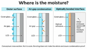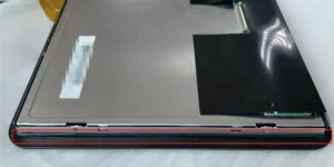
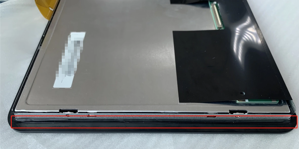
An optically bonded display that looks normal on the bench but develops light leakage or uneven color after installation needs a mechanical review before the LCD is rejected. Compare the same display conditions before and after mounting, then check support points, enclosure flatness, gasket compression, fasteners and edge-seal clearance. A changed image can indicate mounting stress, but bubbles, persistent defects and electrical faults require separate investigation. Use the released assembly drawing to decide the next action.
The useful question is not simply whether the display has been optically bonded. It is what changed when the module became part of the machine. This guide addresses that installation step. For the wider electrical and mechanical stack, see the PCAP touchscreen and LCD integration guide.
Start with a repeatable before-and-after check
Record the module part number and revision, the display timing, brightness setting and test pattern before installation. Keep the viewing angle, ambient light and camera exposure consistent when comparing images. Automatic camera exposure can make a minor edge glow appear much more severe in one photograph than another.
Inspect the unmounted module using the handling and support method approved for that assembly. The LCD, cover glass and bonded stack should not be bent, twisted or supported on an unapproved edge. Photograph any existing nonuniformity so it is not later mistaken for an installation-induced defect.
Repeat the display and touch checks after each defined assembly stage. A useful record distinguishes the supported module, placement in the enclosure, fastening, cable connection and final sealing. The first stage at which the symptom appears often narrows the investigation.
Match the symptom to the next check
| Observation | What to investigate | Next controlled check |
|---|---|---|
| Bright edge or corner appears after fastening | Local load, frame distortion, mounting flatness or uneven compression | Compare the baseline and assembly-stage images; inspect the approved load-bearing surfaces. |
| Uneven color, patches or water-wave-like distortion | Mechanical stress is one possibility; LCD or bonding-process variation may also contribute. | Keep the pattern and viewing conditions fixed. Record whether the defect existed before installation. |
| New bubbles, edge separation or a visible bond boundary | Bond damage, material/process issues or stress transferred into the bonded interface | Stop assembly and document the location. Do not press, heat or rework the area without an approved process. |
| Touch becomes unstable while the image stays normal | Bezel interference, grounding changes, cable routing or controller tuning | Record the installed configuration and run the applicable touch test; a picture alone cannot diagnose touch noise. |
| The same defect is present before and after mounting | The starting module condition, optical stack or display drive conditions | Refer the baseline to the supplier rather than assuming fastening caused the defect. |
A symptom changing after a mechanical adjustment is useful diagnostic evidence, not proof that the assembly is now reliable. Any change must still meet the mechanical, sealing and functional requirements of the released design.
Review where the installation load goes
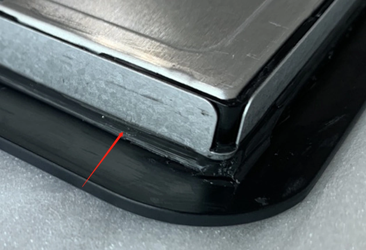
Fasteners and brackets should transfer load through the features designed to carry it. A mounting point on an LCD frame is not automatically an approved attachment point for the complete bonded module. The cover glass, adhesive stack, LCD frame and final enclosure may respond differently to a local load.
Clear the entire module envelope
Include perimeter adhesive, brackets, cable exits and manufacturing tolerances in the fit check. A housing lip that clears the nominal LCD outline may still contact the edge seal or the glass after tolerance accumulation. Do not remove seal material simply to make a module fit.
Control compression and flatness together
Gasket thickness alone does not define its installed behavior. Review the specified material, compression range, contact width, enclosure flatness and tolerance stack together. The support should not introduce concentrated pressure into an unapproved part of the LCD or touch active area.
Use assembly-specific fastener requirements
Confirm screw type, engagement, tightening sequence and torque from the released assembly specification. A general torque chart cannot account for the display frame, thread material, bracket geometry and bonded stack. There is no single torque value that is correct for every optically bonded display.
Choose the mounting method from the complete structure
| Method under review | Design question | Verification focus |
|---|---|---|
| Approved adhesive attachment to the housing | Which surface carries the load, and is the adhesive compatible with that surface? | Bond area, surface preparation, process control, retention and serviceability |
| Rear retention bar or perimeter support | Does the support distribute force without pressing on the active display area? | Contact locations, compression limits, frame flatness and optical changes |
| Module or enclosure brackets | Are the bracket locations part of the approved assembly design? | Bracket stiffness, fastener engagement, load path and cable clearance |
| VESA attachment on a complete monitor | Is the load carried by the monitor housing as intended? | Specified mounting hardware, support structure and rear service space |
| Fastening through LCD side holes | Does the module supplier approve those holes for this bonded assembly? | Frame deformation and the specific fastener requirements; do not assume suitability. |
For equipment that needs an integrated mechanical interface, an open frame touch screen monitor may change the installation task compared with a bare module. The correct choice depends on the supplied assembly and the machine structure, not on the mounting name alone.
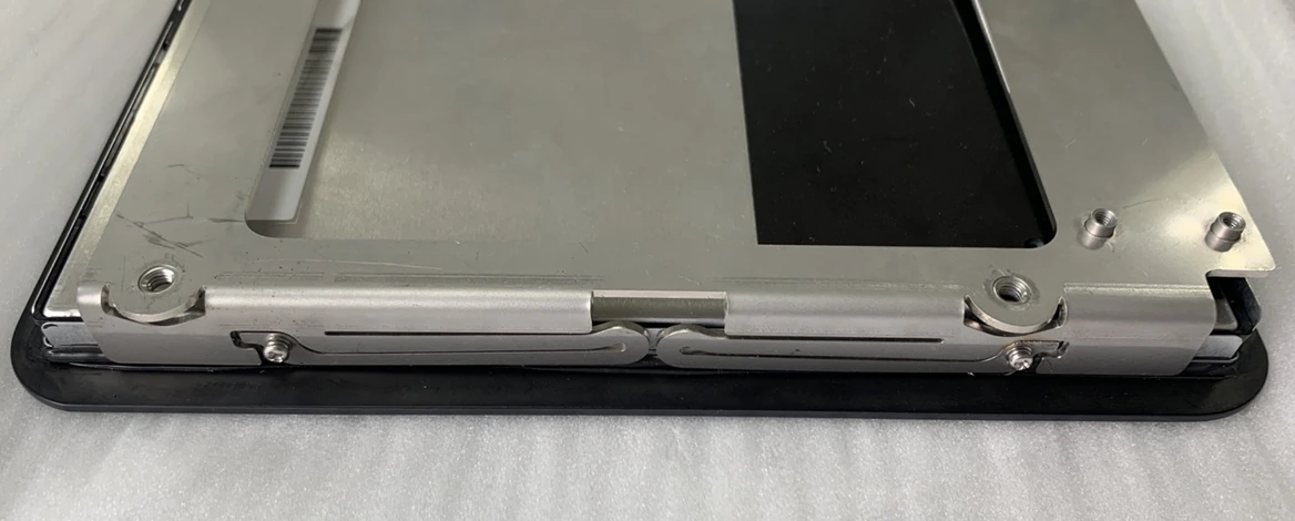
Verify the installed assembly before release
- Preserve the baseline. Retain photographs and display/touch results from the same module before installation.
- Document the build. Record enclosure, bracket, gasket, fastener and module revisions, including the approved assembly sequence.
- Change one factor at a time. Have qualified personnel investigate the mounting conditions using an approved test setup. Do not bend or press the display to make the symptom disappear.
- Repeat optical and touch checks. Check the full active area, edges and corners at the specified operating settings after the final mechanical state is reached.
- Exercise the project conditions. Select environmental and mechanical validation from the machine requirements. Record conditions and acceptance criteria rather than assuming a visual pass proves durability.
- Close the change record. If the mounting design changes, update the drawing and work instructions and confirm the change is repeatable in the pilot build.
The PCAP validation guide covers how to carry the approved configuration into later build stages. A successful bench check should remain traceable to the final enclosure and host configuration.
Engineering checklist for a mounting review
- Module and enclosure drawings identify the approved support and fastening features.
- The tolerance review includes glass, edge seal, brackets, gasket compression and cable exits.
- Before-and-after photographs use consistent display, lighting and camera conditions.
- Touch testing covers the installed system, including edges and corners.
- New bubbles, cracks or separation are recorded and referred for disposition before assembly continues.
- The verification record identifies the build revision, acceptance criteria and any approved corrective action.
Frequently asked questions
Does optical bonding eliminate light leakage?
No. Optical bonding changes the display stack, but LCD nonuniformity, process effects and mounting loads can still affect the image. Acceptance should be defined for the specific module and viewing conditions.
Can loosening a screw confirm the cause?
A controlled adjustment may reveal a relationship with mounting stress, but it does not qualify the final design. Retention, sealing and mechanical requirements must still be satisfied. Follow the assembly procedure rather than experimenting on a powered machine.
Are LCD side mounting holes always unsuitable?
No. Their suitability depends on the complete assembly. Some bonded modules need a different load path; others have approved side mounting provisions. Ask for the module-specific installation drawing.
Is a new bubble definitely caused by installation?
No. Timing helps the investigation but does not establish the root cause. Bonding-process conditions, materials, handling and stress can all require review. Preserve the sample and compare it with the incoming inspection record.
Can I apply a standard screw torque table?
Use the fastener requirements approved for the display assembly. Generic tables do not establish how much load a thin LCD frame or bonded stack can tolerate.
What should I send with a defect report?
Send part and revision identifiers, assembly drawings, fastening and gasket details, before-and-after images, test settings and the assembly stage at which the symptom first appeared. Include touch-test results if the touch behavior also changed.
Engineering basis and limits. This guide draws on EverGlory’s WI-ZJ-019 optical-bonding installation guidance, revision A1 dated January 2, 2025, and its touch-panel/module instructions. The photographs are installation examples. They do not establish a universal mounting method, torque, environmental rating or defect acceptance limit. The released drawing and project validation plan govern the selected configuration.
Send the installation details for engineering review
For a touch display module project, include the module part number, enclosure drawing, fastening locations, gasket specification and the observed symptom. Request an installation review so the mechanical interface and verification inputs can be assessed before the next build.