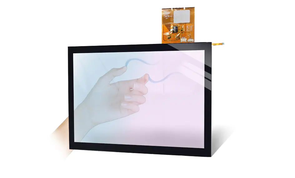
OEM device interface
Custom cover glass, sensor stack, FPC and controller matching for device housings.
A projected capacitive touch panel provides the touch-input layer; it includes an LCD only when quoted as a complete display module. Review cover glass, sensor, controller, USB or I2C interface and cable layout together, then send your drawing for a configuration review.
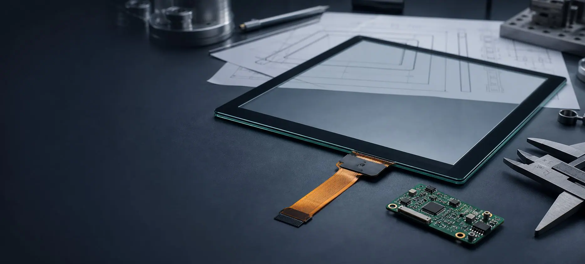
A PCAP project is usually won or lost in the details around glass outline, FPC direction, controller protocol, enclosure gap and operating environment.
Outer shape, black border, logo printing, thickness and AG, AR or AF surface options.
Touch controlUSB HID, I2C, RS232 option, FPC tail direction, connector and firmware tuning.
Module buildWhen the panel must be matched with an LCD, optical bonding or a touch display module.
EnvironmentGlove touch, wet touch, EMI, cleaning, outdoor exposure and sealed-front designs.
Browse PCAP touch panel models and related custom options. If your project needs a different size, glass outline, interface or bonding structure, send requirements for engineering review.
A capacitive touch panel is the core touch interface used in many modern industrial products. Compared with older pressure-based input methods, projected capacitive touch panels (PCAP) offer a cleaner glass surface, better touch responsiveness, support for multi-touch interaction, and a stronger premium feel for OEM equipment.
On this page, you can explore custom capacitive touch panels for industrial HMI systems, self-service terminals, medical devices, EV chargers, and other embedded projects. Depending on the stack design, industrial PCAP solutions can support glove touch, wet touch, water rejection, thicker cover glass, and custom front-surface treatments such as AG, AR, and AF coatings.
A capacitive touch panel can be customized with different cover lens structures depending on the target product and environment.
Real industrial touch performance depends not only on the panel itself, but also on the controller and firmware tuning.
A standard consumer touch panel is not enough for industrial use. System-level fit must be considered early.
The best industrial capacitive touch panel is selected based on the full application, not only the screen size. Buyers should define the operating conditions before finalizing the touch stack.
| Area | Basic Touch Panel | Industrial Capacitive Touch Panel |
|---|---|---|
| Cover Glass | Basic standard glass or consumer-style structure | Custom thickness, shape, black mask, AG/AR/AF options |
| Touch Performance | Standard finger touch | Can be tuned for glove touch, wet touch, and water rejection |
| Durability | General use | Better suited for industrial, public-use, and harsh front surfaces |
| Integration | Limited project flexibility | Designed around OEM drawings and project requirements |
| Reliability Focus | Short-term function | Better suited for long-term industrial deployment |
Modern PCAP can work well with gloves and moisture, but only when the controller and sensor stack are properly tuned for the target environment.
Glass thickness, anti-glare, anti-reflective, and anti-fingerprint coatings directly affect usability, clarity, and durability.
EMI, enclosure pressure, sealing, and cable routing can influence final touch stability as much as the panel itself.
Yes. EverGlory can review custom sensor size, active area, cover-glass outline, printing, FPC direction and controller requirements. Final feasibility depends on the drawing, LCD, enclosure, operating environment and project quantity.
Many PCAP projects can support glove input, wet fingers and water-rejection tuning, but the result depends on the glove, cover glass, sensor, controller settings, grounding and final enclosure. Confirm the intended conditions and validate the complete system.
Provide the LCD model, active and visible areas, outer dimensions, cover-glass drawing, interface, controller or motherboard, FPC direction, mounting structure, operating environment and estimated quantity. These details allow an early integration-risk review.
Tell us your panel size, cover glass requirement, glove or wet-touch conditions, and application environment. We will recommend the right PCAP touch structure for your project.

Small-format PCAP panel for HMI, wall-mounted control and sealed-front device integration.
Read more
Small-format PCAP panel for HMI, wall-mounted control and sealed-front device integration.
Read more
Large or exposed-use touch panel route where front durability and water tolerance matter most.
Read more
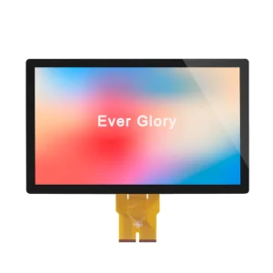
Projected capacitive touch panel option for OEM devices, HMI interfaces and embedded equipment.
Read more
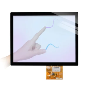
Projected capacitive touch panel option for OEM devices, HMI interfaces and embedded equipment.
Read more
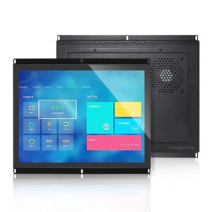
Mid-size PCAP overlay route for kiosks, gaming equipment, control panels and OEM display builds.
Read more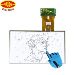
Confirm the cover-glass outline, controller interface and mounting fit against the selected product drawing.
Read more
Confirm the cover-glass outline, controller interface and mounting fit against the selected product drawing.
Read more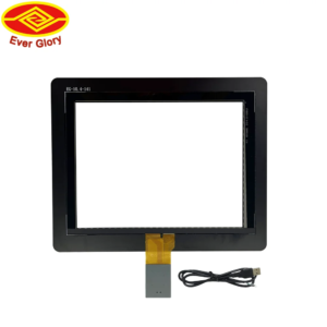
Confirm the cover-glass outline, controller interface and mounting fit against the selected product drawing.
Read more
Confirm the cover-glass outline, controller interface and mounting fit against the selected product drawing.
Read more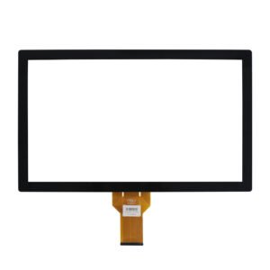
Confirm the cover-glass outline, controller interface and mounting fit against the selected product drawing.
Read more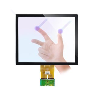
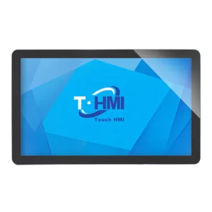
Industrial touch panel size for equipment consoles, machine interfaces and public-use terminals.
Read moreConfirm the practical engineering parameters before choosing a standard touch panel or asking for a custom PCAP build.
| Project requirement | Recommended focus | Why it matters |
|---|---|---|
| Outdoor terminal or kiosk | Durable cover glass, water tolerance, anti-glare surface and vandal resistance | Protects the front surface and keeps touch response stable in exposed public-use equipment. |
| Industrial HMI panel | PCAP controller choice, grounding design, EMI behavior and FPC direction | Reduces unstable touch response when installed near drives, motors, cabinets or metal structures. |
| Medical or clean equipment | Flat cover glass, chemical resistance, glove operation and repeatable wipe-down behavior | Supports cleaner front design and predictable interaction during frequent cleaning. |
| OEM display module | LCD matching, air or optical bonding, flatness, cable routing and long-term supply | Helps avoid mechanical redesign when the touch panel becomes part of a complete module. |
These application examples make it easier to decide whether your project needs a standalone PCAP touch panel, a bonded touch display module or a finished touch screen monitor.
Custom cover glass, sensor stack, FPC and controller matching for device housings.
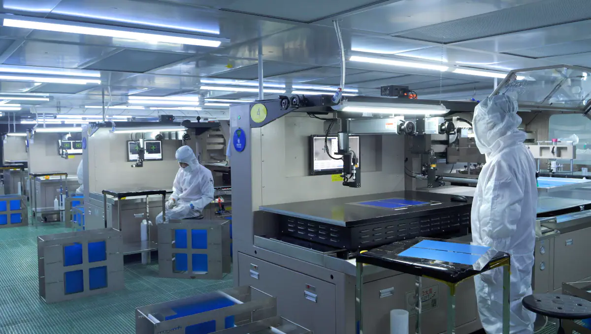
Stable PCAP operation for control panels, automation terminals and factory equipment.
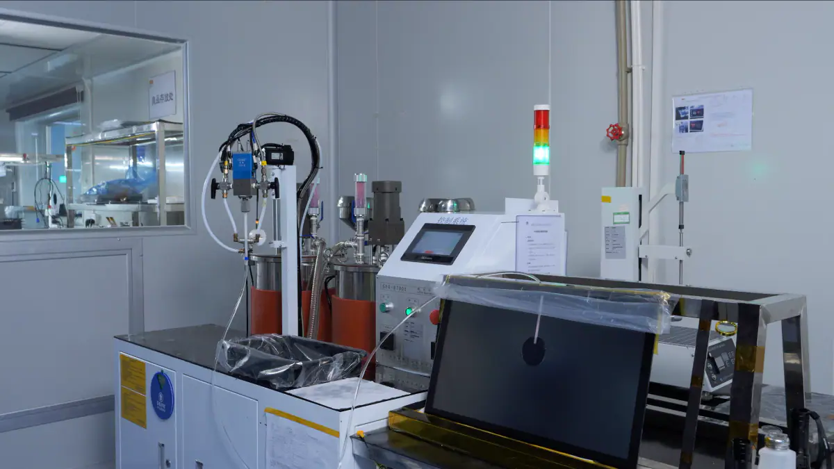
LCD matching and bonding support when the touch panel is part of a complete module.
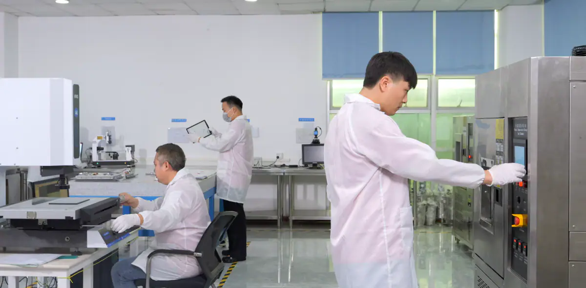
Flat front glass, cleaning behavior and repeatable touch validation for equipment UIs.
If the touch panel alone is not enough, compare the next integration level before sending your project request.
For custom capacitive touch panels, quotation accuracy depends on the glass outline, active area, controller, interface, FPC direction, bonding method and operating environment.
Send RFQ detailsEngineering FAQ
Practical answers for engineers integrating a PCAP touchscreen with an LCD, controller, FPC, metal enclosure and final product assembly.
Ghost touches after installation do not automatically mean the touch sensor is defective. If the bare panel tests normally but the problem appears after assembly, check the integrated system first.
LCD interference, incomplete grounding, a nearby metal enclosure or bezel, unstable FPC routing, and touch controller settings can all change capacitive behavior. Fix the FPC in a stable position, review its distance from power and high-frequency circuits, verify the grounding path, and confirm that metal does not intrude into the sensing area. Controller tuning should be completed only after the mechanical and electrical stack is representative.
Engineering Note: Validate the touchscreen again in the final assembled system, not only as a bare sensor.
The LCD metal frame, touch controller and LCD driver board should generally share a controlled common ground. This helps reduce static accumulation and limits EMI or electrical interference between the display and touch system.
Depending on the final system, the grounding path may use a mounting screw, conductive tape, conductive fabric, conductive foam or a dedicated grounding wire. The connection should be mechanically stable and reviewed together with the enclosure, power design and controller location. Common grounding is an integration measure, not a guarantee that every ghost-touch condition will disappear.
Integration Tip: Confirm the grounding arrangement with the production-representative LCD, controller, board and enclosure, then repeat the Sensor Test.
Fix the touchscreen FPC so it does not move during normal operation, and route it away from high-frequency signal areas and main power circuitry. Avoid sharp folding, repeated movement and a changing relationship between the FPC and nearby metal structures.
An unsecured tail can change its capacitive coupling as the device vibrates or is serviced. A sharp fold can also create mechanical stress that later becomes an intermittent fault. Define the bend radius, fixing points, connector access and metal clearances during the mechanical design review.
Engineering Note: FPC routing should be considered during mechanical design, not only after a touch problem occurs.
Yes. Metal positioned close to a PCAP sensor can affect capacitive sensing, and the edge area is often the most sensitive because the electric field is already influenced by the sensor boundary and enclosure geometry.
The metal bezel should not intrude into the active sensing area. Evaluate the bezel geometry, grounding path, sensor and cover glass together rather than reviewing each item separately. Stable performance also depends on the actual distance and mechanical tolerances in production.
Integration Tip: Validate edge and corner touch response in the final enclosure before pilot production.
Edge touch can become difficult when the front bezel is too thick or the enclosure opening is too small. The finger may no longer cover enough of the edge or corner area to create a reliable touch signal.
Review the front-frame thickness, enclosure opening, mechanical tolerance stack and any UI controls placed close to the display edge. As an engineering reference, the enclosure opening can be designed approximately 2 mm larger than the display visible area, depending on the final mechanical design, while the front-frame thickness should be minimized.
Engineering Note: Test edge controls with the final bezel, glass and production-representative assembly.
Send us the core system details so the engineering review can start with the complete assembly: