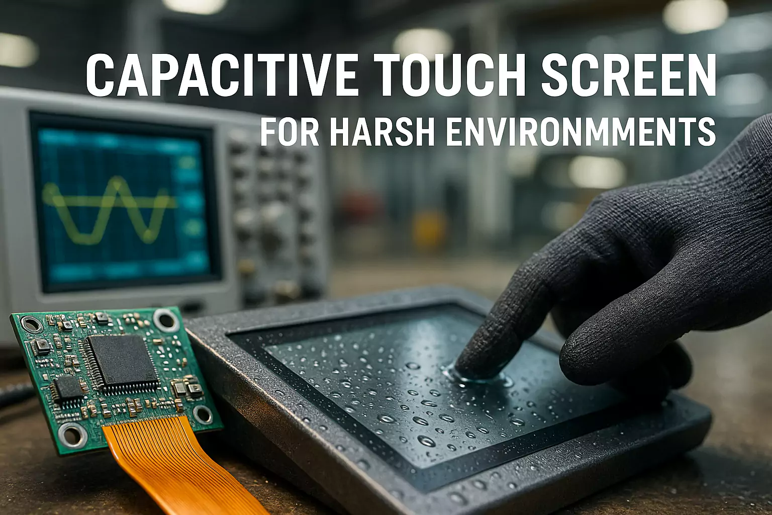
Ghost touch on an industrial touch screen means the system reports touch points when no finger, glove, stylus, or object is actually touching the screen.
In a consumer device, ghost touch is annoying. In an industrial HMI, outdoor kiosk, EV charger, medical device, marine display, or production control panel, it can become a serious integration problem. A false touch may trigger the wrong menu, stop an operation, select the wrong charging option, interfere with a medical interface, or create unstable user experience in the field.
At EverGlory, we often see one important pattern: the touch panel works normally during bench testing, but ghost touch appears after it is assembled into the final machine.
That usually means the problem is not only the touch panel itself. It may come from the full system design, including grounding, LCD noise, cable routing, metal bezel structure, waterproof design, controller tuning, or mechanical pressure.
Quick Answer: Why Does an Industrial Touch Screen Get Ghost Touch?
Industrial touch screen ghost touch is commonly caused by the following system-level factors:
- Poor grounding between the touch controller, LCD frame, LCD driver board and metal enclosure
- EMI from motors, inverters, relays, chargers, power supplies or high-current cables
- LCD noise or backlight interference
- TP and LCD stack-up problems, especially unsuitable air gap or adhesive design
- FPC bending, floating, or passing near high-frequency signals
- Metal bezel edges entering too close to the sensor active area
- Water droplets, rain, cleaning liquid, condensation or wet fingers
- Enclosure pressure, uneven gasket compression or mechanical stress
- Incorrect controller firmware, sensitivity setting or wet-touch tuning
- Long, unshielded or incorrectly routed USB / I2C / signal cables
For OEM projects, the correct approach is not to replace the screen immediately. The correct approach is to test the touch panel, LCD, controller board, enclosure, grounding, cable routing and final working environment as one complete system.
What Is Ghost Touch on an Industrial Touch Screen?
Ghost touch, also called false touch or phantom touch, happens when the touch controller detects a touch signal that does not come from a real user input.
On a projected capacitive touch screen, the controller reads changes in the electric field of the sensor. In an ideal condition, those changes come from a finger, glove, stylus, or other intended input.
In industrial equipment, however, the touch signal can be affected by many external factors, including electrical noise, poor grounding, moisture, metal structures, LCD interference, cable routing, power supply instability, mechanical stress and wrong controller tuning.
Why Ghost Touch Often Appears After Final Assembly
Many OEM engineers first test the touch panel on a desk. The touch panel may work well when it is placed on an insulated surface and connected to a test computer.
But after assembly, the operating environment changes. The touch panel is close to the LCD, the LCD frame may become part of the grounding path, the controller board may be fixed to metal parts, the FPC may bend or touch the enclosure, and power or display signal cables may run near the touch controller.
For this reason, EverGlory recommends that OEM customers do not only test the touch panel before assembly. The final machine should also pass a touch function test after installation and before shipment. For mass production projects, each complete device structure should be tuned and verified before batch assembly.
Cause 1: Poor Grounding Between Touch Controller, LCD and Metal Frame
Poor grounding is one of the most common causes of industrial touch screen ghost touch. In a PCAP touch system, the touch controller needs a stable electrical reference. If the LCD frame, LCD driver board, touch controller and metal enclosure do not share a reliable ground, the touch signal may become unstable.
Typical Symptoms
- Random touch points appearing on the screen
- Touch points jumping near the edge
- Touch becoming unstable when the LCD turns on
- Ghost touch appearing only after installation into a metal housing
- Intermittent false touch when the operator touches the metal enclosure
- Touch instability after changing the power supply or host board
For industrial integration, the LCD metal frame, touch controller and LCD driver board should be connected to a stable common ground. If the controller board cannot be fixed by screws, conductive tape, copper foil, conductive fabric or grounding wires may be needed to create a reliable grounding path.
Engineering Checks
- Is the touch controller properly grounded?
- Is the LCD frame connected to the same ground reference?
- Is the LCD driver board grounded with the touch controller?
- Is the metal enclosure floating?
- Does painting, anodizing, coating or adhesive block electrical contact?
- Does the touch behavior change when an extra ground wire is added?
Cause 2: EMI From Motors, Inverters, Chargers and Power Modules
Industrial machines are full of noise sources: motors, frequency inverters, relays, solenoids, high-current power cables, switching power supplies, EV charging modules, LED backlight drivers, main board power sections, wireless modules and high-speed display signal cables.
These noise sources may interfere with the touch controller, FPC, USB cable, I2C line or sensor signal.
Common Applications Affected by EMI
- Factory automation HMIs
- Outdoor kiosks
- EV charging stations
- Car wash machines
- Marine control panels
- Industrial cabinets
- Medical equipment
- Heavy-duty control terminals
| Test | Purpose |
|---|---|
| Test the touch screen outside the enclosure | Confirms whether the bare touch module is stable. |
| Test with LCD on and LCD off | Checks whether LCD or backlight noise affects touch. |
| Test with motor / inverter / charger on and off | Identifies noise from power components. |
| Move touch cable away from power cables | Checks whether routing causes interference. |
| Use an independent stable power supply | Checks power noise influence. |
| Retune the controller with final machine assembled | Improves noise margin under real conditions. |
Touch controller boards and FPC cables should not pass directly above or below high-frequency signals, main power sections, or high-current cables. If crossing is unavoidable, the routing should be planned carefully and shielding may be required.
Cause 3: LCD Noise and Touch-LCD Stack-Up Problems
In many OEM projects, ghost touch does not appear until the touch panel is assembled with the LCD. This is because the LCD, backlight, driver board and display signal cables may all create electrical noise.
Important Stack-Up Factors
- Distance between the touch panel and LCD
- Whether the adhesive is insulating
- Whether the LCD frame is properly grounded
- Whether the touch sensor is too close to the LCD
- Whether the LCD model has strong noise characteristics
- Whether the system uses air bonding or optical bonding
- Whether the controller firmware was tuned with the final LCD stack
- Whether the display signal cable is routed close to the touch signal path
For air-bonded structures, the air gap between the touch panel and LCD should be designed carefully. If the gap is too small or the adhesive is not suitable, LCD interference may cause false touch, jumping points or broken lines.
For optical bonding, the touch panel and LCD become one integrated module. This can reduce internal reflection, improve display readability and improve structural stability, but the bonding process and edge sealing must be controlled carefully.
Key point for OEMs: changing the LCD model, bonding method, cover glass thickness or enclosure structure may require touch controller retuning.
Related solution: custom touch display module integration and optical bonding for industrial touch displays.
Cause 4: FPC Bending, Floating or Contact With Metal Parts
The FPC is often ignored, but it can directly affect touch stability. In industrial equipment, the FPC may be bent, folded, pressed, stretched or left floating inside the enclosure. If it moves during vibration or touches metal parts, the capacitance environment may change and cause unstable touch signals.
Common FPC-Related Problems
- FPC folded too sharply
- FPC moving inside the enclosure
- FPC touching metal housing intermittently
- FPC routed near power cables
- FPC passing close to the main board power area
- FPC crossing high-frequency signal lines
- FPC not fixed after assembly
- FPC damaged during installation
EverGlory recommends that FPC routing should be fixed during assembly. Avoid repeated bending, sharp folding, or leaving the FPC free to move. If unavoidable bending is required, insulation should be used where layers or metal structures may contact each other.
Cause 5: Metal Bezel Too Close to the Sensor Active Area
Many industrial devices use metal front frames for strength. However, metal frames can create touch interference if the structure is not designed correctly.
If the metal edge enters too close to the sensor active area, it may affect the electric field at the edge of the touch panel. This can cause edge ghost touch, edge dead zones, corner touch failure, random touch points near the frame, or reduced touch accuracy near the border.
OEM Checks
- Does the metal frame enter the sensor active area?
- Is the view window large enough?
- Is the front frame too thick?
- Is the edge area pressed by the housing?
- Is there enough clearance between the active area and metal structure?
- Does edge touch improve when the front frame is removed?
For transparent touch panels used in embedded structures, if the front frame is too thick, the user’s finger may not reach the edge and corner areas accurately. In this case, the mechanical opening, cover glass printing, UI layout and touch active area should be reviewed together.
Cause 6: Water, Rain, Cleaning Liquid and Wet Fingers
For outdoor, wash-down, public kiosk, car wash, marine, bathroom, food processing and EV charging applications, water is a major cause of false touch.
Waterproof does not automatically mean wet-touch stable. Waterproof design focuses on preventing water from entering the device. Wet-touch stability focuses on preventing water droplets, water films or wet fingers from being recognized as false input.
Common Water-Related Causes
- Water droplets staying on the glass
- Water collecting at the lower metal frame
- Cleaning liquid forming a conductive film
- Condensation between the touch panel and LCD
- Wet hands touching the screen
- Rainwater bridging between the bezel and touch surface
- Recessed frame design trapping water
- Controller not tuned for wet-touch operation
For outdoor and wet environments, vertical installation is generally better than flat installation because water drains more easily. AF or AS coating can help reduce water accumulation on the glass surface. A full-flat front design is usually better than a recessed metal frame because it allows water to drain away instead of collecting at the edge.
Related solution: IP65 waterproof touch monitor for outdoor and wash-down applications.
Cause 7: Mechanical Pressure, Gasket Compression and Assembly Stress
Ghost touch may also come from mechanical pressure. In some designs, the touch panel is pressed unevenly by the front frame, gasket, bracket, or screws. The problem may not appear during open-frame testing but appears after final assembly.
Typical Signs of Mechanical Stress
- Ghost touch near one edge
- Touch point stays in one area
- False touch appears after screws are tightened
- Touch returns to normal when the front frame is loosened
- Touch becomes unstable after thermal cycling or vibration
- LCD light leakage or bonding stress appears together with touch instability
For bonded touch display modules, the LCD should not be forced by side screws or uneven mechanical pressure. The module should be fixed in a way that reduces stress on the LCD and bonding layer.
Cause 8: Controller Firmware and Sensitivity Not Tuned for the Final Device
A PCAP touch controller is not a “one-setting-fits-all” component. The correct controller setting depends on sensor size, cover glass thickness, bonding method, LCD model, air gap, enclosure material, grounding condition, cable length, glove requirement, wet-touch requirement, EMI environment, operating temperature and humidity.
If the controller is tuned only on a bench, it may not perform well in the final machine. This is why EverGlory recommends real-machine testing before mass production. The touch controller should be checked and tuned with the final LCD, housing, cable routing, grounding design and application environment.
| Application | Touch Tuning Priority |
|---|---|
| Factory HMI | EMI tolerance, grounding stability, glove operation |
| EV Charger | Rain stability, wet hand operation, outdoor sunlight use |
| Medical Device | Stable input with cleaning agents and controlled sensitivity |
| Outdoor Kiosk | Water drainage, public-use durability, false touch prevention |
| Marine Display | Humidity, salt-air exposure, water film handling |
Controller tuning should balance sensitivity and stability. Higher sensitivity is not always better. If sensitivity is too high, the screen may become more vulnerable to noise, water, or metal interference.
OEM Troubleshooting Checklist for Industrial Touch Screen Ghost Touch
Before replacing the touch screen, OEM engineers should check the complete system.
| Step | What to Test | What It Helps Identify |
|---|---|---|
| 1 | Test the touch panel on an insulated surface | Confirms basic touch panel and controller function. |
| 2 | Run sensor test before assembly | Checks whether the hardware is normal. |
| 3 | Install into the enclosure and test again | Identifies structure, grounding and pressure problems. |
| 4 | Test with LCD on and off | Checks LCD noise and backlight interference. |
| 5 | Test with final power supply | Checks power noise and grounding behavior. |
| 6 | Turn motors, relays, chargers or inverters on and off | Checks EMI influence. |
| 7 | Check grounding between LCD frame, controller and driver board | Confirms common ground stability. |
| 8 | Inspect FPC routing and cable position | Finds bending, movement, or signal interference. |
| 9 | Loosen the front frame or screws and retest | Checks mechanical pressure. |
| 10 | Test dry, wet, rain, spray and cleaning conditions | Confirms wet-touch performance. |
| 11 | Test with final cable length | Checks cable noise and signal stability. |
| 12 | Retune controller firmware in the final machine | Improves performance under real operating conditions. |
What Information Should You Send to EverGlory for Ghost Touch Analysis?
If your industrial touch screen shows ghost touch after installation, sending the right information helps our engineers identify the likely cause faster.
- Touch screen size
- LCD model and interface
- Cover glass thickness
- Bonding method: air bonding, frame bonding, or optical bonding
- Controller IC or controller board model
- Connection method: USB, I2C, UART, etc.
- Photos of front frame, back structure, FPC routing and controller board position
- Photos showing grounding points
- Short video of the ghost touch behavior
- Description of when the issue appears
- Final application: HMI, kiosk, EV charger, medical, marine, car wash, etc.
- Required operation: glove touch, wet hand touch, thick cover glass, AG glass, optical bonding, or high brightness
How EverGlory Helps OEM Customers Reduce Ghost Touch Risk
EverGlory manufactures and customizes PCAP touch panels, touch display modules, industrial touch monitors and touch panel PCs for OEM industrial applications.
- Custom PCAP touch sensor design
- Cover glass and sensor stack-up review
- Touch controller selection and tuning
- LCD and touch integration support
- Optical bonding
- Waterproof front structure suggestions
- Grounding and FPC routing recommendations
- Wet-touch and glove-touch tuning
- Touch module testing before shipment
- Real-machine debugging before mass production
Our goal is not only to supply a touch panel. Our goal is to help OEM customers build a stable touch interface that works reliably in the final machine.
Facing ghost touch after enclosure assembly?
Send us your LCD model, touch size, cover glass thickness, bonding method, controller type, cable routing photo and short failure video. Our engineers can help identify the likely root cause.
Engineering Update: Grounding, LCD Noise and FPC Routing Checks
Quick answer: most industrial PCAP ghost touch cases are not caused by the sensor alone. The common root causes are unstable grounding, LCD or power noise coupling into the sensor, FPC routing near high-noise areas, water on the front glass, or mechanical stress after the panel is installed into the enclosure.
1. Grounding path
Check whether the touch controller, LCD frame and metal chassis share a stable reference ground. Painted metal, anodized brackets, foam tape or floating controller boards can break the discharge path and reduce noise margin.
2. LCD noise path
LCD backlight, power supply ripple and high-brightness drive conditions can change the sensor baseline. Compare sensor data with different brightness levels, different power supplies and the LCD turned on/off.
3. FPC routing
Keep the FPC away from inverter lines, LED backlight cables, switching power modules and sharp metal edges. Fix the cable path so it cannot float, fold sharply or rub against conductive parts after assembly.
| Question to verify | What to compare | Useful evidence for diagnosis |
|---|---|---|
| Does LCD noise interfere with PCAP? | Touch raw data with LCD off, LCD on, low brightness and high brightness. | Sensor Test screenshots, noise logs, power supply condition and LCD part number. |
| Can FPC routing cause ghost touch? | Original cable path vs rerouted/insulated/fixed FPC path. | Before/after photos, repeated touch test result and failure location map. |
| Is the issue caused by grounding? | Floating controller board vs controller-LCD-chassis common ground. | Ground continuity check, metal frame contact points and ESD/EMI symptoms. |
Engineering Isolation Tests for Industrial PCAP Ghost Touch
When ghost touch appears only after the touch panel is installed into the final machine, changing the touchscreen immediately is usually the wrong first step. The fastest diagnostic method is to change one system condition at a time and record whether the false touch disappears, becomes weaker, or remains unchanged.
Quick answer: industrial PCAP ghost touch should be diagnosed as a system integration issue. Start with symptom isolation, then test LCD state, motor or VFD operation, enclosure assembly, grounding, FPC routing, wet surface behavior and cable length before changing controller firmware.
| Isolation Test | What to Change | If Touch Becomes Stable | Likely Direction |
|---|---|---|---|
| LCD ON / OFF | Keep PCAP powered, switch LCD/backlight condition | Noise decreases with LCD OFF | LCD/backlight interference |
| Motor / VFD ON / OFF | Compare touch during equipment idle and operation | Failure follows VFD/motor operation | Conducted or radiated EMI |
| Open-frame / Enclosure | Test before and after final assembly | Only fails after assembly | Grounding, bezel, pressure or cable routing |
| Original / Common Ground | Compare grounding configuration | Common ground improves stability | Ground reference problem |
| Original / Re-routed FPC | Move FPC away from power/high-frequency cables | Touch becomes stable | FPC coupling/interference |
| Dry / Wet Surface | Test controlled water conditions | Failure only occurs with water | Wet-touch tuning or drainage |
| Short / Long USB Cable | Compare cable length/routing | Short cable improves stability | Signal integrity or EMI |
Engineering rule: Change only one variable at a time. If grounding, cable routing, LCD condition and firmware are changed together, the project team may solve the symptom without identifying the actual root cause.
LCD ON/OFF Isolation Test
A practical way to isolate LCD-related interference is to keep the PCAP controller and host system powered while comparing touch behavior with the LCD or backlight in different operating states. If false touch, line instability or sensitivity changes significantly when the LCD/backlight state changes, the LCD system should be treated as a potential noise source rather than immediately retuning the touch controller.
- Step 1 — Touch panel only: PCAP + controller + host, with the LCD not operating.
- Step 2 — LCD powered: LCD and backlight are on, while other high-power devices remain off.
- Step 3 — Full machine operating: LCD + backlight + PSU + motor/VFD/charger operate in the real working condition.
Do not finalize PCAP firmware using only a bench setup. Final tuning should be verified with the actual LCD, backlight, power supply, enclosure and cable routing used in mass production.
Recommended Ground Reference for an Industrial PCAP Assembly
A stable reference path should be reviewed from Touch Controller → LCD Metal Frame → LCD Driver Ground → Equipment Chassis / Metal Enclosure.
A PCAP grounding problem is often not caused by “too little ground,” but by an unstable or inconsistent electrical reference between the controller, LCD and machine chassis.
Correct
- Stable controller ground
- LCD frame connected to defined system ground
- LCD driver board shares controlled ground reference
- Chassis grounding path is deliberate and repeatable
- Ground path remains consistent between prototype and production
Risky
- Controller floating on double-sided adhesive
- LCD frame floating electrically
- Ground connection depending on accidental metal contact
- FPC shield touching chassis intermittently
- Prototype and production units using different grounding paths
PCAP FPC Routing: Wrong vs Recommended Layout
PCAP FPC routing should be treated as part of the touch sensing system, not as ordinary wiring. Moving the FPC after firmware tuning can change the electrical environment and may require re-validation.
Case Study Evidence Interface
The following case study structure is prepared for future real project evidence. It should not be published as a claim until the engineering team has real application data, isolation-test records and final validation results.
Future URL suggestion: /case-studies/industrial-hmi-ghost-touch-emi-troubleshooting/
| Case Study Field | Information Required Before Publication |
|---|---|
| Application | Real application and operating environment. |
| Initial Configuration | LCD, PCAP, cover glass, controller, interface, enclosure and power environment. |
| Failure | Actual failure symptom and when it appears. |
| Isolation Test | Real controlled tests and observations. |
| Root Cause | Engineering conclusion supported by evidence. |
| Engineering Changes | Actual modifications to grounding, routing, structure, controller or power design. |
| Final Validation | Real validation method and result, without invented pass data. |
| Lessons for OEM Engineers | Reusable engineering learning from the project. |
Conclusion
Industrial touch screen ghost touch is rarely caused by one simple factor.
In many OEM projects, the touch panel may pass bench testing but show false touch after it is assembled with the LCD, controller board, metal frame, power system and final enclosure.
The most common causes include grounding problems, EMI, LCD noise, FPC routing, water accumulation, mechanical pressure, metal bezel interference and controller tuning mismatch.
Before replacing the touch panel, OEMs should test the complete system step by step. If your touch screen works normally before assembly but shows ghost touch in the final device, EverGlory can help review your touch panel structure, LCD stack-up, grounding design, FPC routing, waterproof design and controller tuning before mass production.
FAQ
What causes ghost touch on an industrial touch screen?
Industrial touch screen ghost touch can be caused by poor grounding, EMI, LCD noise, water droplets, FPC routing, metal bezel interference, mechanical pressure, unstable power supply, or controller tuning that does not match the final device.
Why does my touch screen work before assembly but fail after installation?
If the touch panel works before assembly but shows ghost touch after installation, the issue is often related to the final enclosure, grounding, LCD interference, FPC position, metal frame, gasket pressure, or cable routing.
Can waterproof touch screens still have false touch in rain?
Yes. Waterproof and wet-touch stability are different. A screen may prevent water ingress but still detect rainwater, cleaning liquid, or water accumulation near the frame as false touch if the structure and controller tuning are not optimized.
Can EMI cause ghost touch on an HMI screen?
Yes. Motors, inverters, relays, chargers, switching power supplies, backlight drivers, and high-current cables can interfere with PCAP touch signals. Proper grounding, shielding, cable routing, and controller tuning are important.
Does optical bonding help reduce ghost touch?
Optical bonding can improve the touch-display stack, reduce internal reflection, improve ruggedness, and eliminate the air gap between touch panel and LCD. However, the full design still needs proper grounding, controller tuning, and mechanical integration.
Should I replace the touch panel when ghost touch appears?
Not immediately. First test the touch panel outside the enclosure, check grounding, LCD noise, FPC routing, cable position, water conditions, mechanical pressure, and controller settings. Many ghost touch issues are caused by system-level integration rather than a defective touch panel.
Troubleshooting: engineering decision summary
Quick answer
Ghost touch is normally diagnosed as a system problem, not by replacing one component first. Check power and grounding, host/interface behavior, LCD or charger noise, mechanical pressure, moisture paths, controller settings and enclosure changes in a controlled sequence.
Inputs to confirm
- Reproduce the fault and record the exact configuration
- Separate power, host, noise, mechanical and moisture variables
- Retest one controlled change at a time and retain the result
Evidence boundary
A generic tuning value or controller change is not a universal fix. Escalate with the host, stack drawing, logs and test conditions when the cause remains unclear.
Related engineering guides
- PCAP Controller, Glove Touch and Touch Failure Troubleshooting Guide
- Touch Controller Board Issues: Common Causes and Troubleshooting for Industrial Touch Screens
- Why PCAP Touch Sensitivity Drops After LCD Lamination and How to Fix It
- How to Install an Industrial Touch Screen Protector Film Correctly
Project next step: Review the relevant product or solution scope, the validation evidence boundary, and then send the project inputs for engineering review.